In this lab, explore the foundational concepts of IP addressing, a critical component of modern networking. Learn how IPv4 addresses are structured, including the distinction between network and host portions, and practiced converting between binary and decimal formats. The lab covers key topics such as subnetting, address classes, and private vs. public IP ranges.
Cybrary is a well established and free IT training platform with several intuitive labs to explore
A paid subscription with more advanced labs is available as well outside the scope of this platform
Head to https://www.cybrary.it to create a free account for learning available on their platform
Head to IP Addressing Basics to complete this lab for yourself or perform on your homelab below
Quick Links:
Requirements:
• Windows PC w/ Internet Connection
• USB Flash Drive w/ at least 8GB Capacity
• Second PC with at least 2 GB of memory and 2 CPU cores
In this lab we will explore the building blocks of modern networking: The TCP/IP and ARP Models
TCP stands for Transmissions Control Protocol and IP stands for Internet Protocol respectively
ARP stands for Address Resolution Protocol, each have their roots in the early days of networking
Back then networks were constructed at great cost using custom hardware and proprietary software
In the 90s the Internet Engineering Task Force (IETF) worked with vendors to create open standards
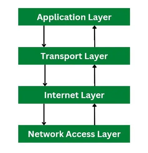
1. The TCP / IP Networking Model
TCP/IP is a suite of networking protocols that govern how data is transmitted between devices
It is a layered protocol, meaning it is organized into four distinct areas of differing function
• Application - Human interface to network resources
• Transport - Provides reliable communication and error handling
• Network - Moves packets between devices on different networks
• Network Interface - Moves packets between devices on the same network
TCP/IP protocols enable data to be broken into packets and reassembled at the receiving device
The suites flexibility and scalability have contributed to widespread adoption in the internet:
2. Transmission Control Protocol (TCP)
The Transmission Control Protocol provides a reliable, connection-oriented communication framework
It establishes a communication channel between devices and ensures that data is sent and received
TCP uses port numbers to distinguish between the many different services running on the systems:
|
Port |
Protocol |
Service |
|
20 |
TCP |
File Transfer Protocol (Data) |
|
21 |
TCP |
File Transfer Protocol (Control) |
|
22 |
TCP/UDP |
Secure Shell (SSH) |
|
23 |
TCP/UDP |
Telnet Protocol |
|
25 |
TCP/UDP |
Simple Mail Transport Protocol (SMTP) |
|
53 |
TCP/UDP |
Domain Name System (DNS) |
|
69 |
UDP |
Trivial File Transfer Protocol (TFTP) |
|
80 |
TCP |
HyperText Transfer Protocol (HTTP) |
|
88 |
TCP |
Kerberos - Authenticating Agent |
|
110 |
TCP |
Post Office Protocol v3 (POP3) |
|
123 |
UDP |
Network Time Protocol (NTP) |
|
135 |
UDP/TCP |
Microsoft RPC Locator Service |
|
137 |
UDP/TCP |
NetBIOS Name Service |
|
138 |
UDP/TCP |
NetBIOS Datagram Service |
|
139 |
UDP/TCP |
NetBIOS Session Service |
|
143 |
UDP/TCP |
Internet Message Access Protocol 4 (IMAP4) |
|
161 |
UDP/TCP |
Simple Network Management Protocol (SNMP) |
|
162 |
UDP/TCP |
SNMPTRAP |
|
389 |
UDP/TCP |
Lightweight Directory Access Protocol (LDAP) |
|
443 |
TCP |
HTTP over SSL/TLS (HTTPS) |
|
445 |
TCP |
Microsoft Active Directory |
|
445 |
UDP |
Microsoft SMB File Sharing |
User Datagram Protocol offers faster, connectionless communications without delivery guarantees
3. Internet Protocol Suite
The Internet Protocol is responsible for moving data packets from a source to a destination address
It does using routers which are special devices that can forward packets across different networks
IP Addresses are used in this process, today there are both IPv4 and IPv6 addressing schemes in use
IPv4 is a 32-bit address made up of four octets and a subnet mask while IPv6 uses massive 128-bits
An octet is a number from 0 to 255, the subnet mask's purpose is to signal which octet is the host:
|
Network |
Host |
|
|
IP Address: Subnet Mask: |
192.168.10 255.255.255 |
.100 .0 |
In the example above, 192.168.10.100 is the IP Address, and 255.255.255.0 is the Subnet Mask
A 255 in the Subnet Mask means the octet is part of the network, while a 0 means part of the host
Hosts on the same network can speak to each other directly using Address Resolution Protocol (ARP)
Hosts on different networks must have their messages forwarded across networks using a router:
|
Network |
Host |
|
|
IP Address: Subnet Mask: |
192.168.10 255.255.255 |
.100 .0 |
|
Network |
Host |
|
|
IP Address: Subnet Mask: |
192.168.10 255.255.255 |
.5 .0 |
|
Network |
Host |
|
|
IP Address: Subnet Mask: |
192.168.11 255.255.255 |
.5 .0 |
In the example above the first and second hosts share the same network and can reach each other
The third host is located on a different network and would thus need a router to reach the others
It is common to see '255.255.255.0' written as /24 when it comes to network subnetting and addressing
4. Routing & Subnetting
For this lab you need to understand that an IP Address is made up of two parts: a network and a host
Only hosts on the same network can speak to each other without a router or some layer 3 interaction
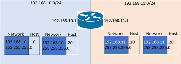
In the example above, 192.168.10.10 can speak directly to 192.168.10.20 without any sort of routing
However 192.168.10.10 will need a router or layer 3 interaction to communicate with 192.168.11.10
Notice the router itself has an IP of 192.168.10.1 which is known as the gateway IP ending with 1
Notice also that the router has two IP Addresses, which are the gateway addresses for each network
Routers do not need to be a part of a network to route packets towards it, routers can chain to reach
Devices on a local network communicating with other devices on the same network is use MAC Addresses
Media Access Control (MAC) Addresses are 12-digit hexadecimal and unique numbers labelling devices
Address Resolution Protocol (ARP) is used to map local IP Addresses to corresponding MAC Addresses:
1. A host broadcasts an ARP request to the local network
2. When the target device sees the ARP request, it replies with an ARP response
3. After receiving the ARP response, the requesting device stores an IP->MAC mapping
This mapping is stored in the ARP Cache which is used to avoid sending ARP Requests unnecessarily
Entries in the ARP Cache typically have a timeout, after which they are considered stale and removed
With the MAC Addresses known, they sending device can encapsulate IP Packets with Ethernet Frames
Once encapsulated these can be sent directly to the target device using the destination MAC Address
Now that we have covered the theory, let's dive into the hands-on part and create virtual networks
5. Create Fedora Linux Live USB
Fedora is a popular Open-Source Linux distribution which is highly customizable and free to download
Maintained by the Fedora Project and originally a fork of Red Hat Linux, it aims to be the leading edge
You can use the operating system without having to install it onto your hard drive with a live USB
Download Fedora Workstation ISO: Fedora Official Download
Download Rufus Disk Imaging Tool: Rufus Official Download
Insert USB Flash Drive, run rufus.exe, select target drive, select Fedora Workstation ISO, Start:

Remove USB Flash Drive and Insert into second PC. Start PC and press hot boot key on startup:
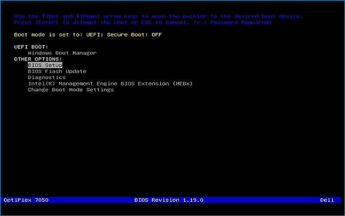
Select UEFI USB Flash Boot. Allow Fedora to load and scroll to select the Fedora Live option:

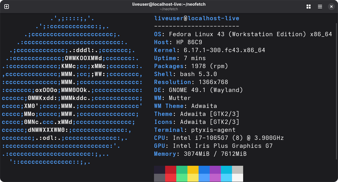
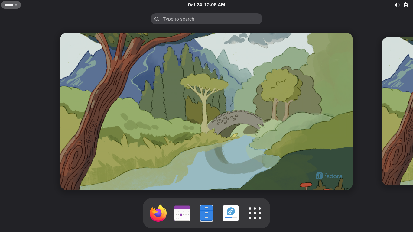
Now allow your workstation a moment to load and you will be taken to the Fedora Desktop Environment:
This live system won't save anything to your PC's hard drive and we will complete the lab here
For the GNS3 Application in the later sections of this lab to work properly, we need installation
6. Fedora Workstation Full-Install
From the Fedora Workstation Live Desktop, click the fourth icon at the bottom to begin installation
Choose your keyboard language from the installation menu and click next, select your disk below:
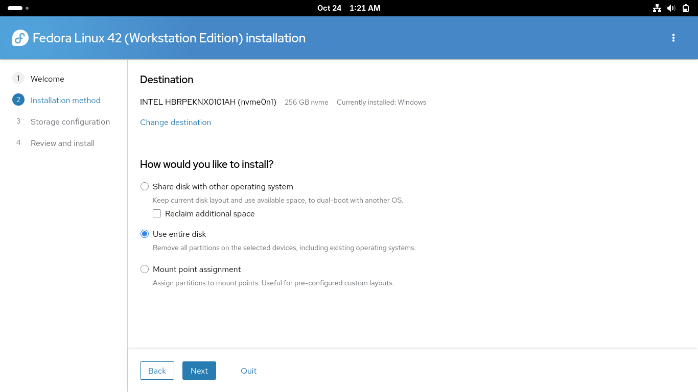
Make sure you select the option to use the entire disk above in order to allow Fedora enough space
Proceed by clicking next, for a quicker installation select not to encrypt the drive and hit next:
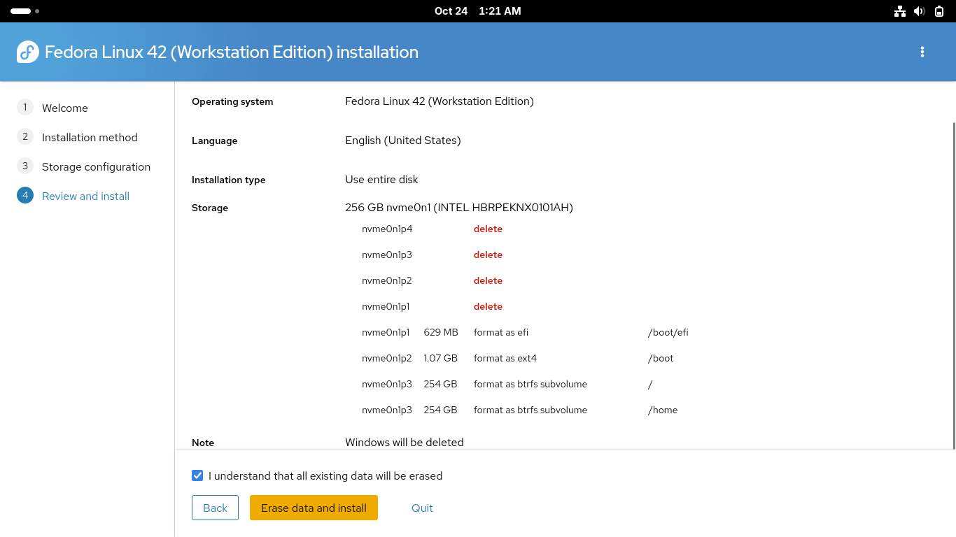
Click on the checkbox to confirm that all existing data will be erased, click erase data and install
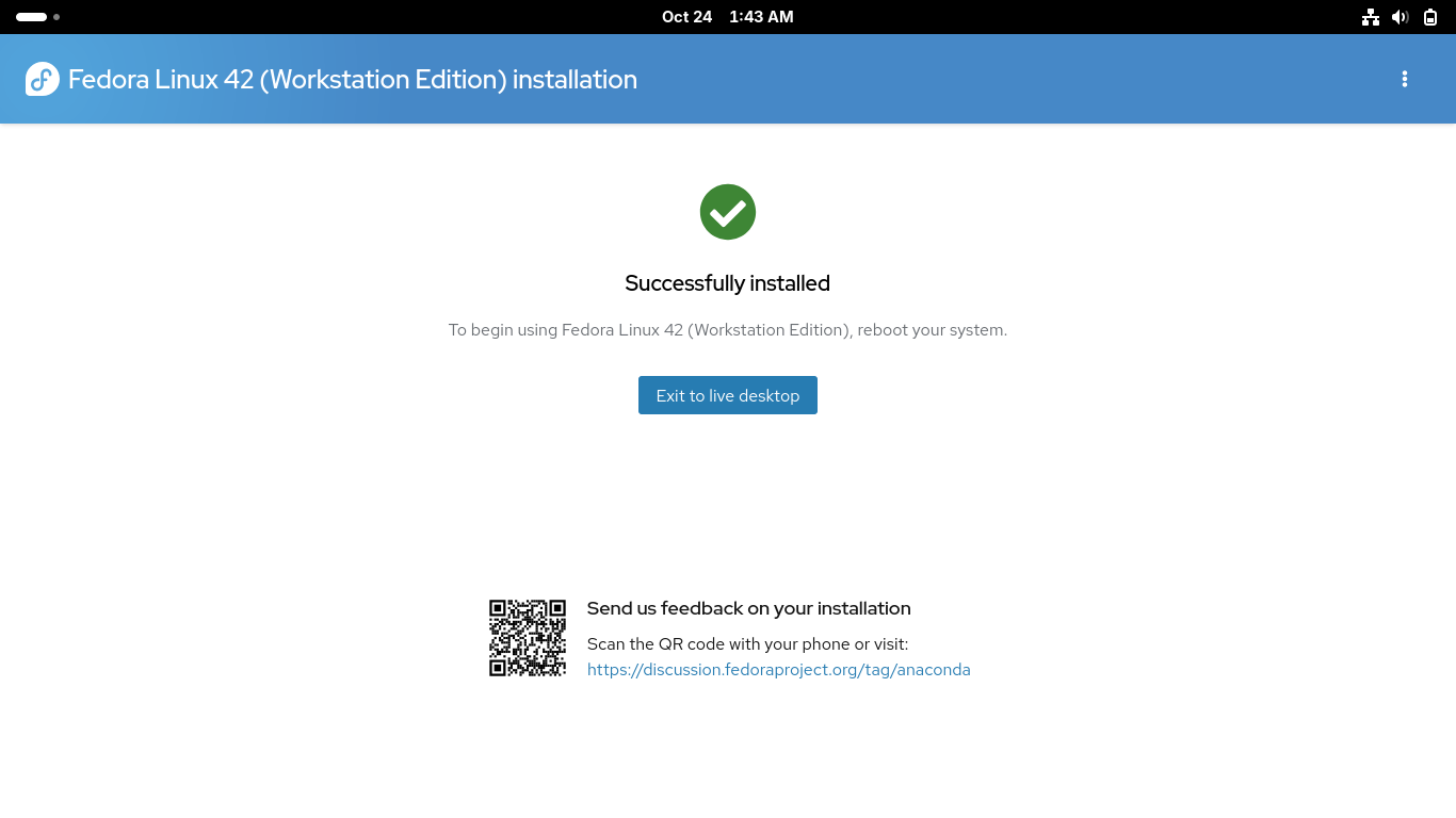
This process will take some time, once completed reboot your PC to enter into your new fedora system
Once rebooted you will need to complete the first time setup including language, time zone and repo
You will also create your user account for the system. Make sure you enable third party repositories
7. Install GNS3 & Local VPCS Server
In this section you will practice analyzing a TCP/IP network topology using GNS3 network simulator
GNS3 is a free and open-source network emulation software that allows you to design and test networks
To get started with creating simulated network environments we must install the dependencies and GUI
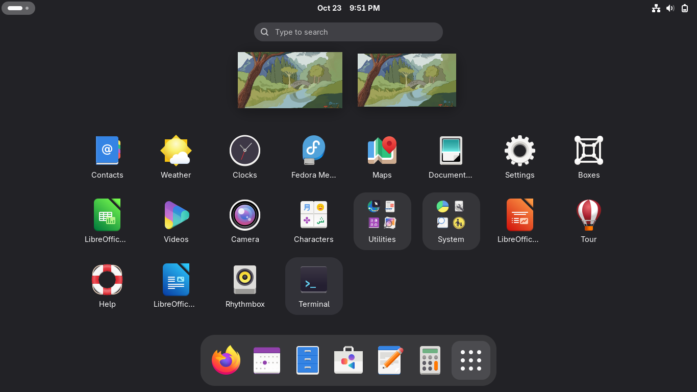
From the Fedora Desktop Environment click on the nine dots in the bottom right to view applications:
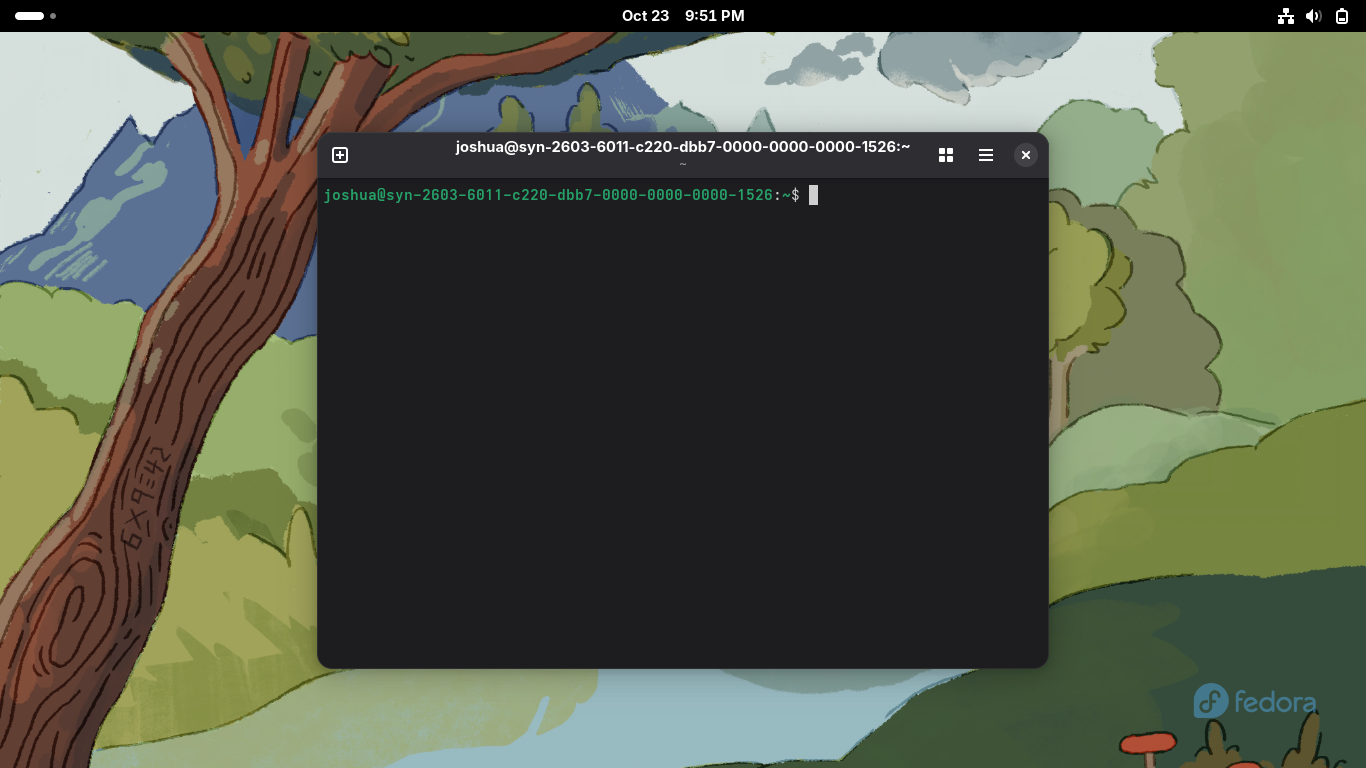
The Terminal is where we can execute CLI commands using the Bourne Again Shell scripting language:
Fedora uses the DNF package manager to install software and update system packages through commands
Run the following command from the Fedora Workstation Terminal to update all the available packages:
user@host:~$ sudo dnf -y upgrade --refresh
Run the following commands from the Fedora Workstation Terminal to install the GNS3 dependencies:
user@host:~$ sudo dnf -y install git gcc cmake flex bison
user@host:~$ sudo dnf -y install elfutils-libelf-devel libuuid-devel libpcap-devel
user@host:~$ sudo dnf -y install python3-tornado python3-netifaces python3-devel python-pip python3-setuptools python3-PyQt4 python3-zmq
GNS3 uses Wireshark for packet capturing and analysis functions. Ensure that Wireshark is installed
Run the following command from the Fedora Workstation Terminal to install the Wireshark Tool:
user@host:~$ sudo dnf -y install wireshark
Run the following command from the Fedora Workstation Terminal to install GNS3 server and GNS3 GUI:
user@host:~$ sudo dnf -y install gns3-server gns3-gui
VPCS is a Virtual PC Simulator which allows you to simulate DHCP and ping when using the GNS3 tool
The tool must be installed using an emulator utility called dynamips which can create custom binaries
Run the following commands from the Fedora Workstation Terminal to install the dynamips emulator:
user@host:~$ git clone https://github.com/GNS3/dynamips
user@host:~$ cd dynamips
user@host:~/dynamips$ mkdir build
user@host:~/dynamips$ cd build
user@host:~/dynamips/build$ cmake ..
user@host:~/dynamips/build$ sudo make install
Run the following commands from the Fedora Workstation Terminal to install the VPCS tool with dynamips:
user@host:~/dynamips/build$ wget https://liquidtelecom.dl.sourceforge.net/project/vpcs/0.8/vpcs_0.8b_Linux64
user@host:~/dynamips/build$ mv vpcs_0.8b_Linux64 vpcs
user@host:~/dynamips/build$ chmod +x vpcs
user@host:~/dynamips/build$ sudo cp vpcs /usr/local/bin/
We now have the GNS3 tool and the various dependencies and addons installed to our Fedora Workstation
Run the following command from the Fedora Workstation Terminal to open GNS3 in the background:
user@host:~$ gns3 &

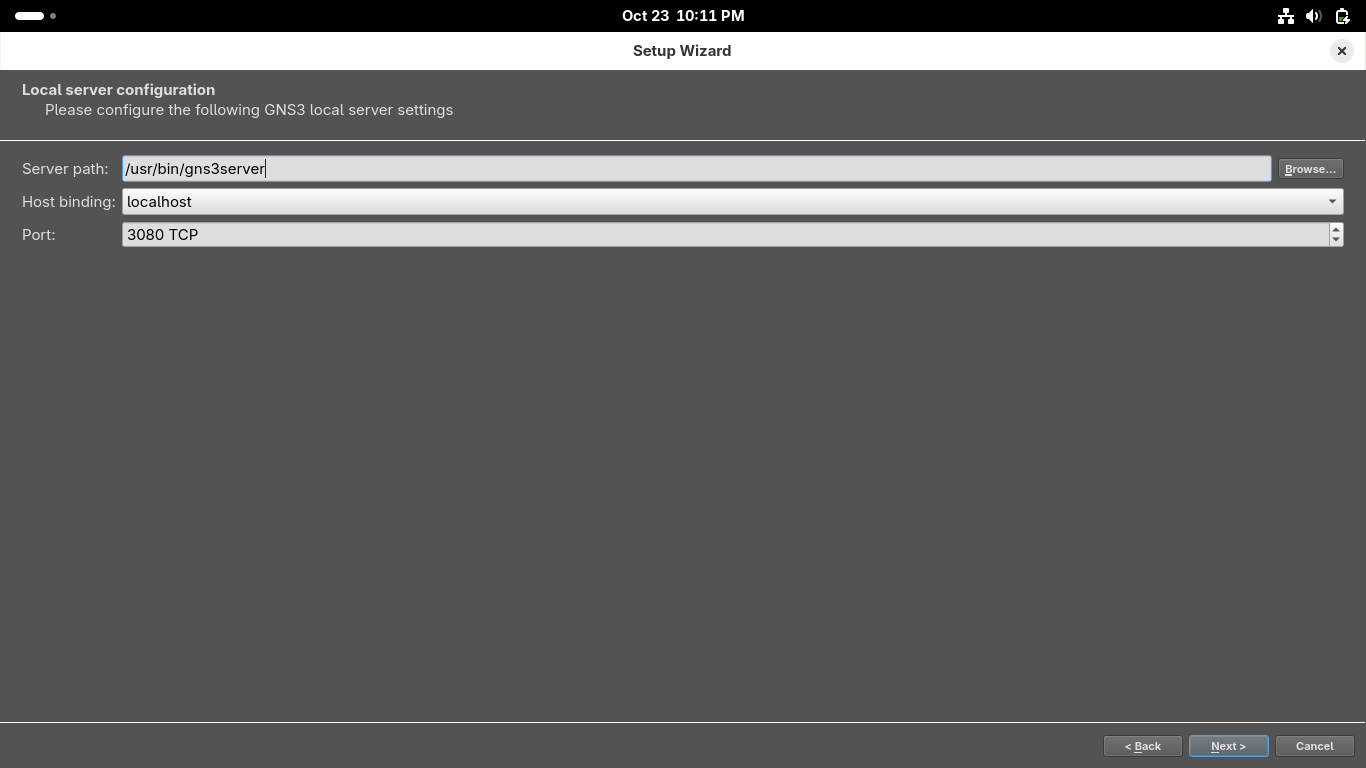
When GNS3 opens up you will be directed to the setup wizard, select 'Run the topologies on my computer'
On the second page use '/usr/bin/gns3server' as the local server path, use host 127.0.0.1 and port 3080:
On the configuration success page click next, then on the New appliance template page click on finish:
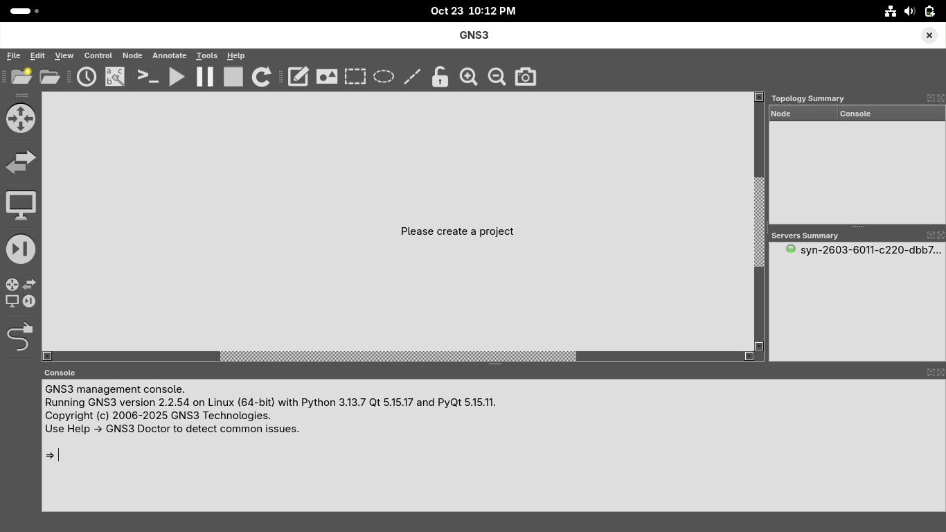
We now have full network emulation along with a virtual PC simulator to create virtual machines for us
8. Create a Virtual Network Environment
To begin our analysis of networking topology we must first create the environment we will be analyzing
From the GNS3 GUI window click on File > New Blank Project > title your project as Project1 and hit ok:

We must import appliances in order to simulate them on our environment, head to File > New Template

Install an appliance from the GNS3 server > OpenWRT > Install > Install the appliance on local computer
Click next and choose the /usr/bin/qemu-system-x86_64 (v9.2.4) Qemu Binary > Click Next > OpenWRT 23.05.0

Click on image file displayed as missing and click on Download to be taken to your browser to download
Once downloaded head back into GNS3 and click refresh and proceed to install the OpenWRT router appliance
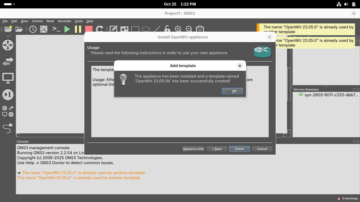
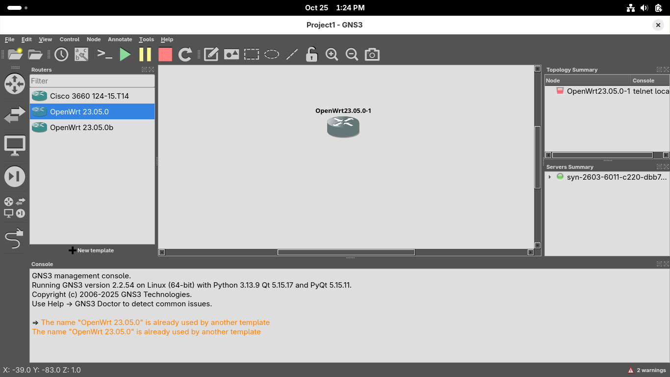
Click on the 'Browse all devices' menu option from the left of the screen and drag and drop our router:
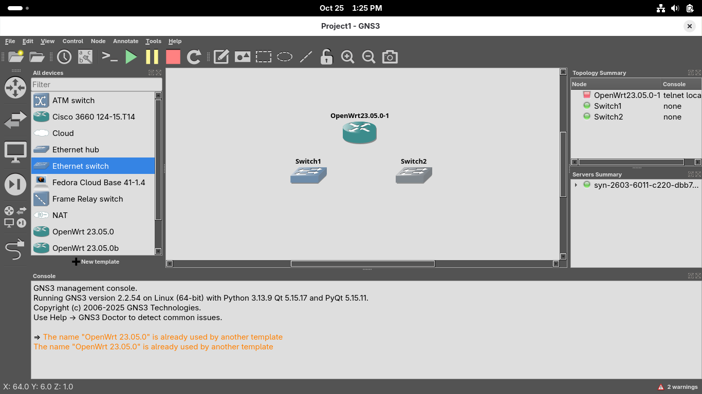
In the same way drag and drop two Ethernet Switches to stand on each side of our newly created router:
We will now add some virtual systems to act as hosts on our network on which we can get remote shells
From GNS3 GUI Window head to File > New Template > Install an appliance from the GNS3 server > Guests:

Navigate to select the Fedora Cloud Base guest, install > Install the appliance on your local computer:
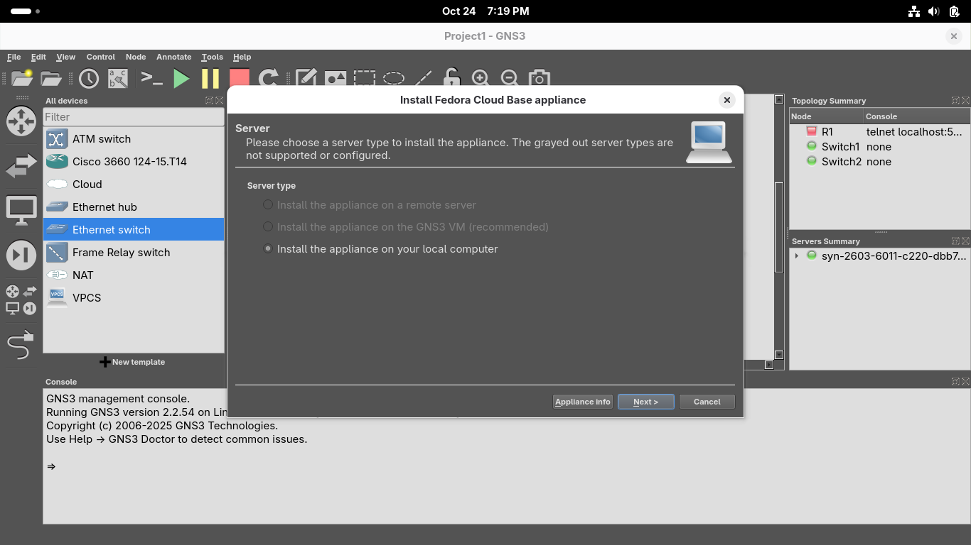
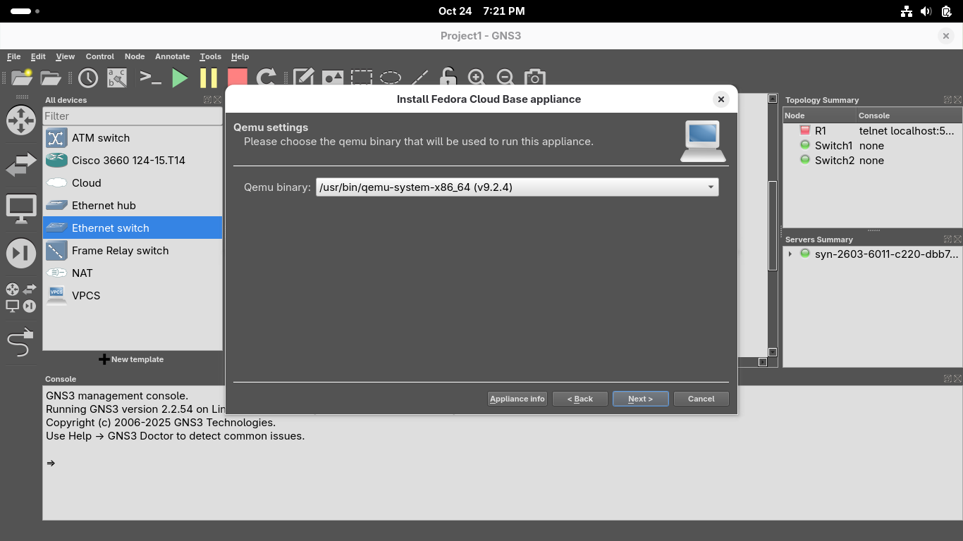
From the Install Fedora Cloud Base appliance menu, select the /usr/bin/qemu-system-x86_64 binary option:
Click on the two lines underneath Fedora Cloud Base version 41-1.4 and click on Download for each one:
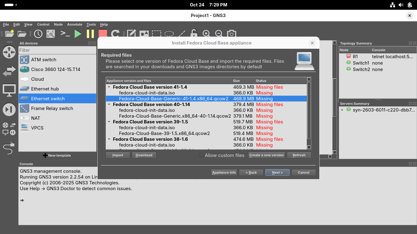
The Download button will take you to a link in your systems default browser firefox to download these
Once the download for each of these files has completed, close your browser and hit refresh in GNS3:
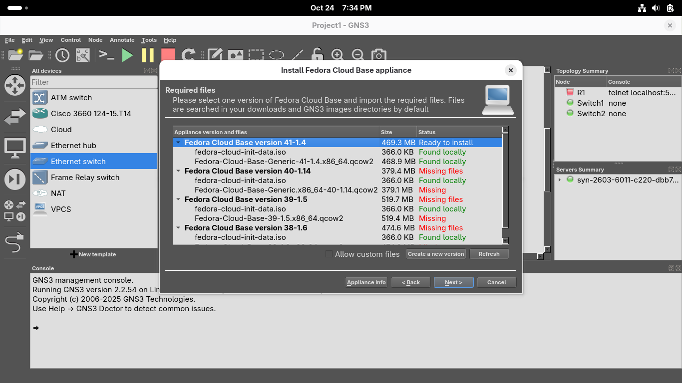
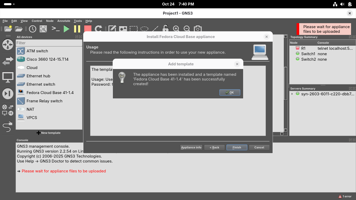
Click next and confirm you'd like to install the appliance, once installed click finish from the menu:
In the same way drag and drop four Fedora PCs to stand to each side of the router and the switches:
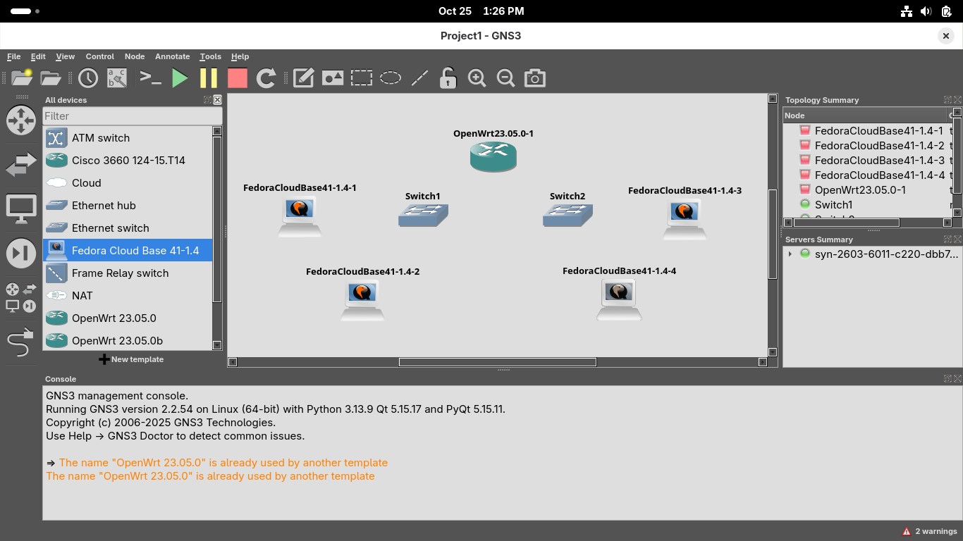
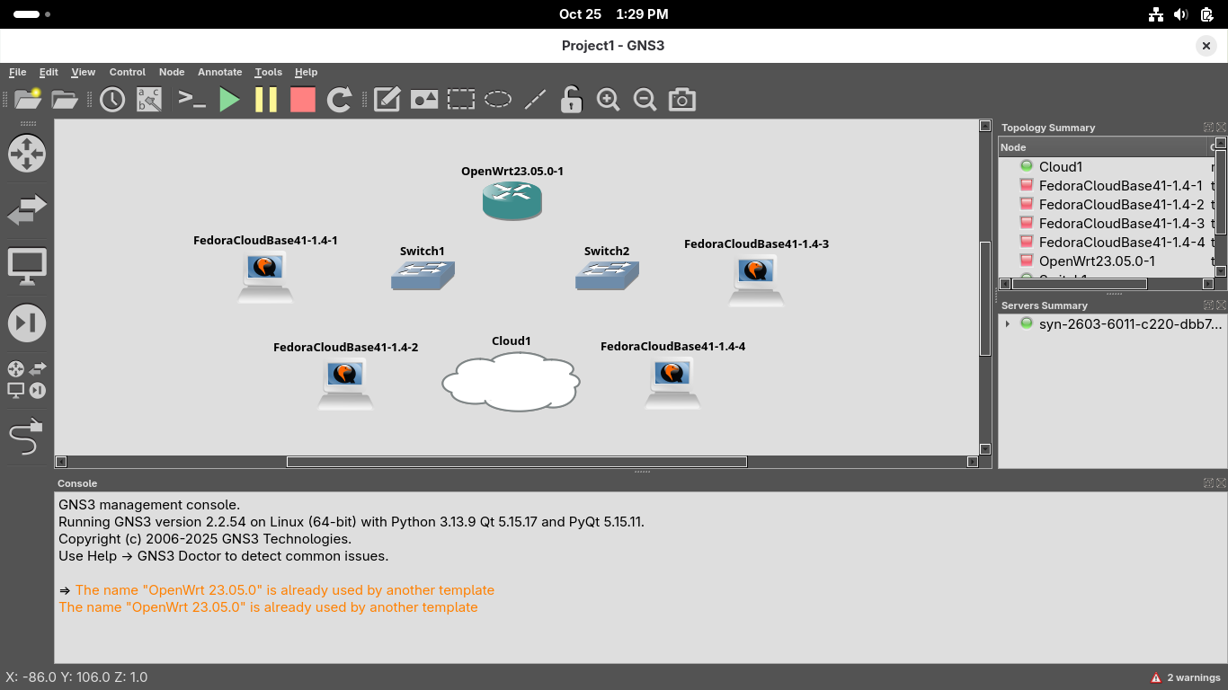
In the same way drag and drop a cloud interface to sit flush and easily accessible to the router:
Use the wire icon on the left of the GNS3 GUI window to create links between the devices like below
Make sure the router uses link 1 specifically to connect to the cloud since that is the WAN interface
Use the interfaces eth0 and eth2 on the OpenWRT router to create a link to each of our network switches:
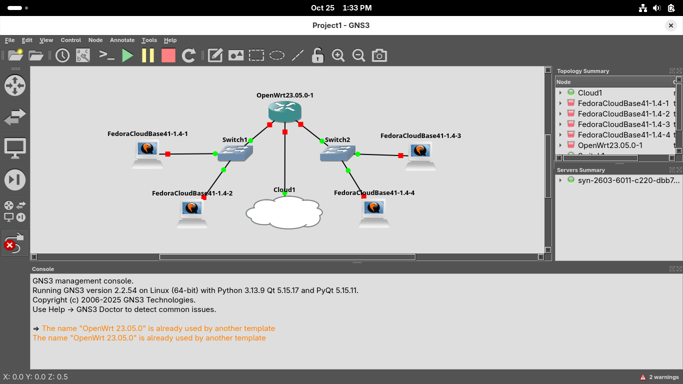
Lastly click the green Start button at the top of the GNS3 GUI window to start all of the node devices:
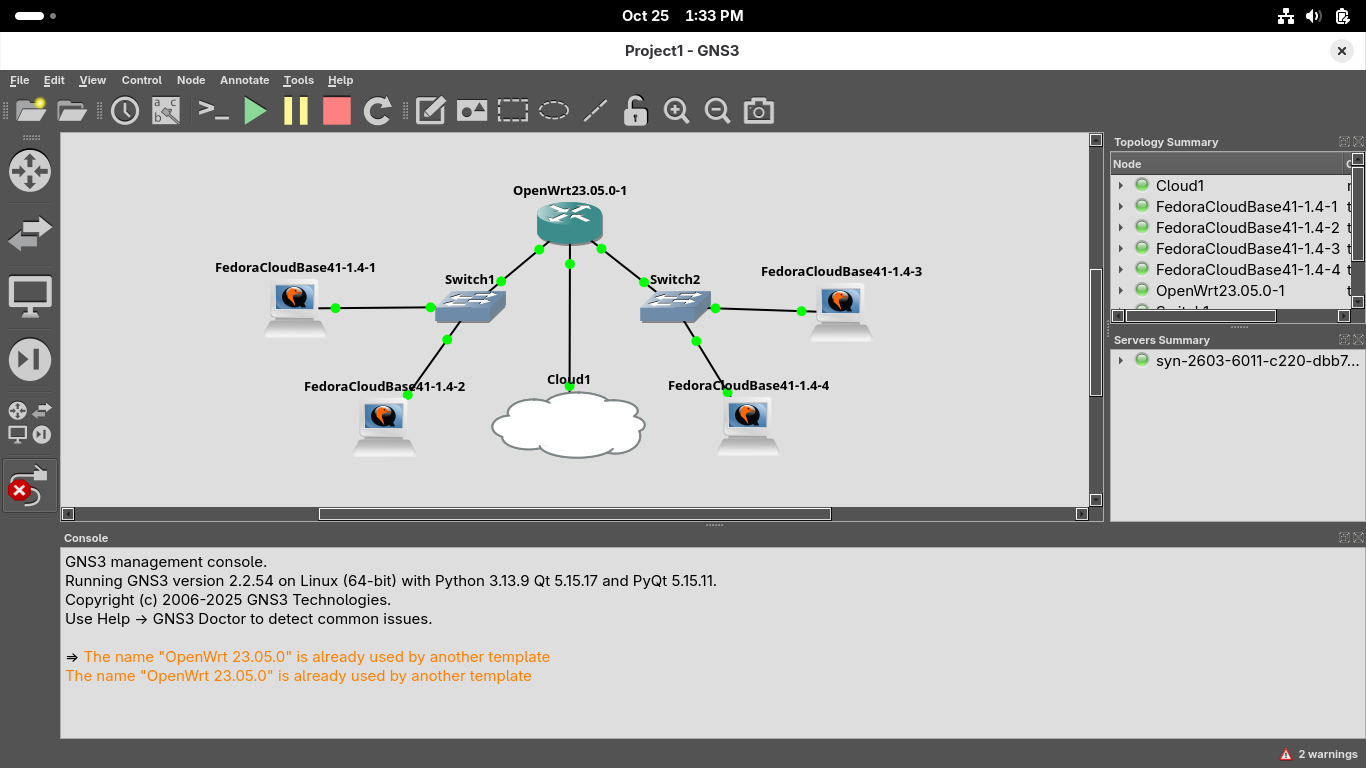
You will see all of the connection points turn green which indicates that the systems are powered on
9. Install KVM Hypervisor & Xterm
In order for us to use KVM and QEMU virtual machines inside GNS3 we the to install the KVM Hypervisor
Run the following command from the Fedora Workstation Terminal to check if your CPU supports VMs:
user@host:~/dynamips/build$ cat /proc/cpuinfo | egrep "vmx|svm"
If your see the terms vmx or svm appear anywhere in the output of the previous command you are good
Run the following commands from the Fedora Workstation Terminal to install the KVM / QEMU packages:
user@host:~/dynamips/build$ sudo dnf -y install bridge-utils libvirt virt-install qemu-kvm
user@host:~/dynamips/build$ sudo dnf -y install libvirt-devel virt-top libguestfs-tools guestfs-tools
Run the following commands from the Fedora Workstation Terminal to start and enable the KVM daemon:
user@host:~/dynamips/build$ sudo systemctl start libvirtd
user@host:~/dynamips/build$ sudo systemctl enable libvirtd
Run the following commands from the Fedora Workstation Terminal to install the Xterm VM Manager:
user@host:~/dynamips/build$ sudo dnf -y install virt-manager
user@host:~/dynamips/build$ sudo dnf -y install xterm
Now we are clear to proceed with the lab and have the ability to use our virtual Fedora Workstations
10. Create Second Subnetwork w/ OpenWRT
We want to examine how packets are routed between two networks in the next section for the lab exercise
To do this we will configure two different Subnetworks on the left and right sides using OpenWRT router
Right click on the OpenWRT23.05.0-1 router and select the console option, allow the system to load
Run the following commands from the OpenWRT console to create a second LAN interface using eth2 port:
root@OpenWrt:/# uci set network.lan2=interface
root@OpenWrt:/# uci set network.lan2.proto='static'
root@OpenWrt:/# uci set network.lan2.ipaddr='192.168.2.1'
root@OpenWrt:/# uci set network.lan2.netmask='255.255.255.0'
root@OpenWrt:/# uci set network.lan2.device='eth2'
root@OpenWrt:/# uci set network.lan2.ip6assign='60'
Run the following commands from the OpenWRT console to add DHCP support for our lan 2 interface:
root@OpenWrt:/# uci set dhcp.lan2=dhcp
root@OpenWrt:/# uci set dhcp.lan2.interface='lan2'
root@OpenWrt:/# uci set dhcp.lan2.start='100'
root@OpenWrt:/# uci set dhcp.lan2.limit='150'
root@OpenWrt:/# uci set dhcp.lan2.leasetime='12h'
Run the following commands from the OpenWRT console to create a firewall zone for our lan 2 interface:
root@OpenWrt:/# uci add firewall zone
root@OpenWrt:/# uci set firewall.@zone[-1].name='lan2'
root@OpenWrt:/# uci set firewall.@zone[-1].network='lan2'
root@OpenWrt:/# uci set firewall.@zone[-1].input='ACCEPT'
root@OpenWrt:/# uci set firewall.@zone[-1].output='ACCEPT'
root@OpenWrt:/# uci set firewall.@zone[-1].forward='REJECT'
root@OpenWrt:/# uci add firewall forwarding
root@OpenWrt:/# uci set firewall.@forwarding[-1].src='lan2'
root@OpenWrt:/# uci set firewall.@forwarding[-1].dest='wan'
Run the following command from the OpenWrt console to commit the uci changes and restart the network:
root@OpenWrt:/# uci commit
root@OpenWrt:/# /etc/init.d/network restart
root@OpenWrt:/# /etc/init.d/dnsmasq restart
root@OpenWrt:/# /etc/init.d/firewall restart
Run the following commands from the OpenWrt console to enable forwarding between the subnetworks:
root@OpenWrt:/# uci add firewall forwarding
root@OpenWrt:/# uci set firewall.@forwarding[-1].src='lan'
root@OpenWrt:/# uci set firewall.@forwarding[-1].dest='lan2'
root@OpenWrt:/# uci commit
root@OpenWrt:/# /etc/init.d/firewall restart
root@OpenWrt:/# uci add firewall forwarding
root@OpenWrt:/# uci set firewall.@forwarding[-1].src='lan2'
root@OpenWrt:/# uci set firewall.@forwarding[-1].dest='lan'
root@OpenWrt:/# uci commit
root@OpenWrt:/# /etc/init.d/firewall restart
Our router is now creating a two tiered segmented network for us to study the interactions within
11. Analyze Network Topology
With our environment deployed, let's begin to explore how these systems and networking devices interact
In this part of the lab we will open a terminal on each device and examine its networking configuration
From the GNS3 topology window, right-click FedoraCloudBase41-1.4-1 and select the Console option:
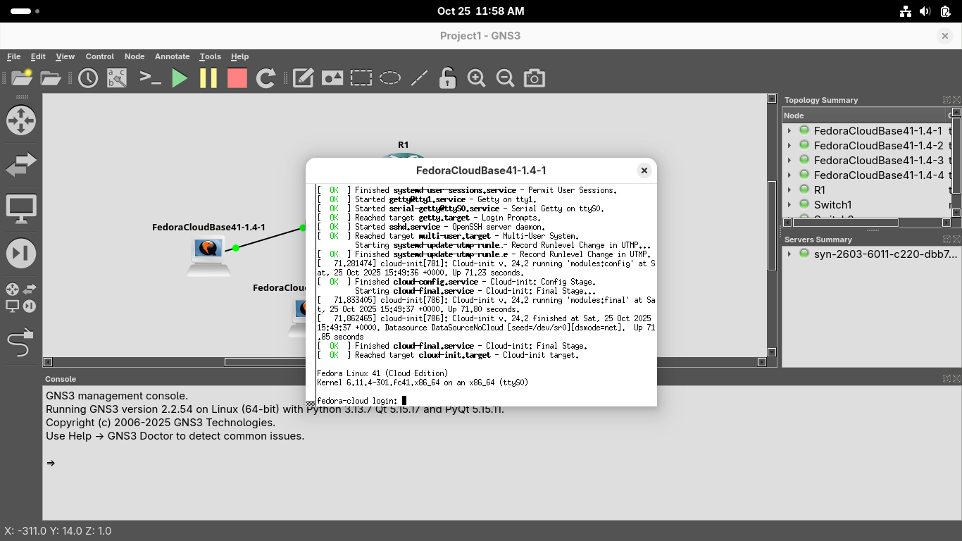
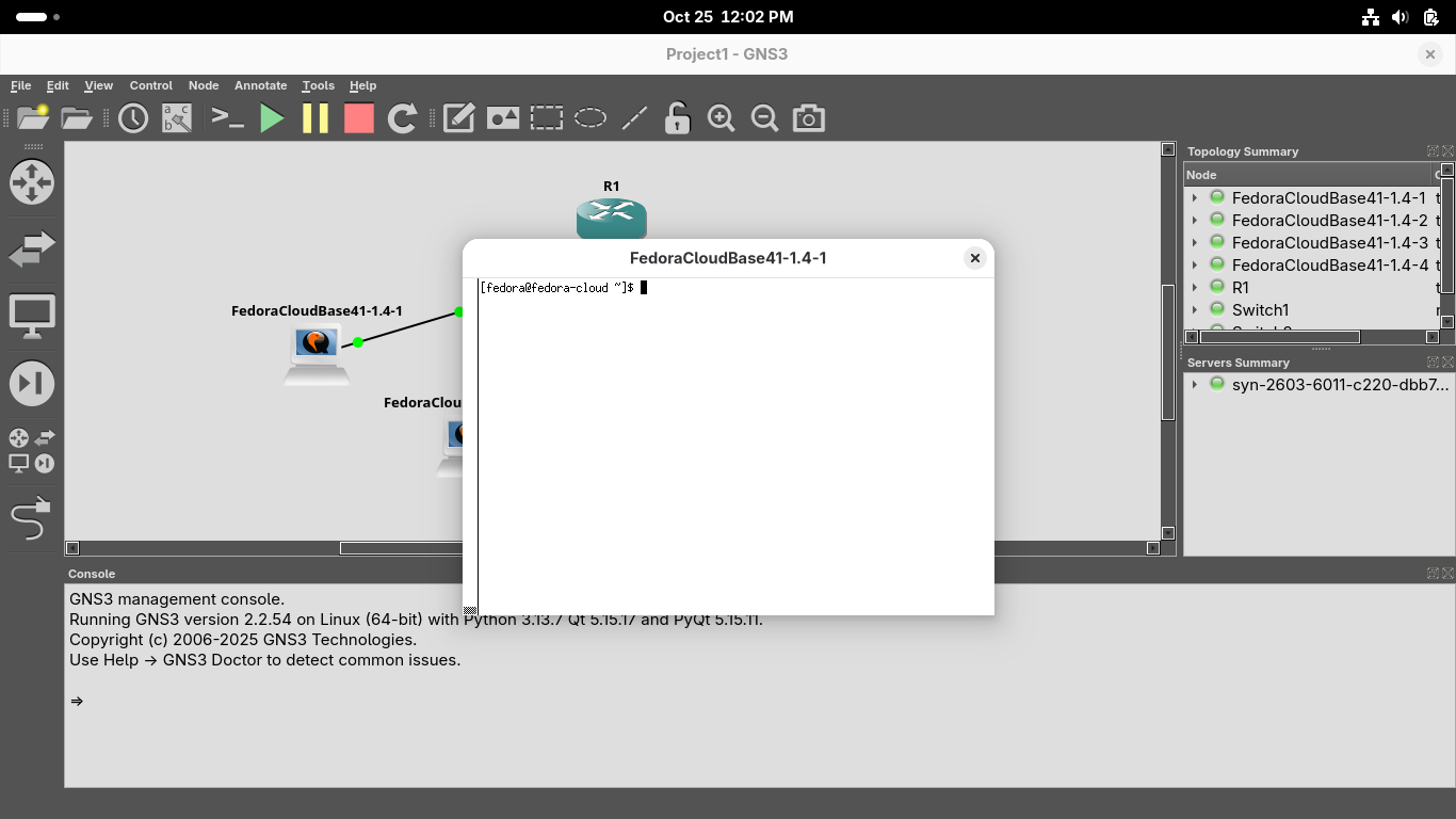
Log in to the system with the default credentials which are username: fedora, password: fedora:
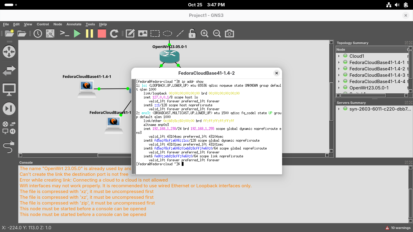
Run the following command from the Virtual Xterm Terminal to display this hosts network configuration:
[fedora@fedora-cloud ~]$ ip addr show
Resulting Output:

You should see two interfaces displayed, ens3 the primary interface, and lo the loopback interface
ens3 is the primary interface for this system and represents the ethernet link to the switch device
lo is the loopback interface, its a virtual interface used by the system to communicate with itself
Take note of the MAC Address (link/ether), IP Address and Subnet Mask (inet) for the ens3 interface
Because the Subnet Mask of /24 is 255.255.255.0 we can tell that this is host 150 on 192.168.0.0/24
Note that because this is a vitrual environment GNS3 changes MAC addresses each time it is reloaded
Close the Xterm window and right click the second workstation and run ip addr show from the console:
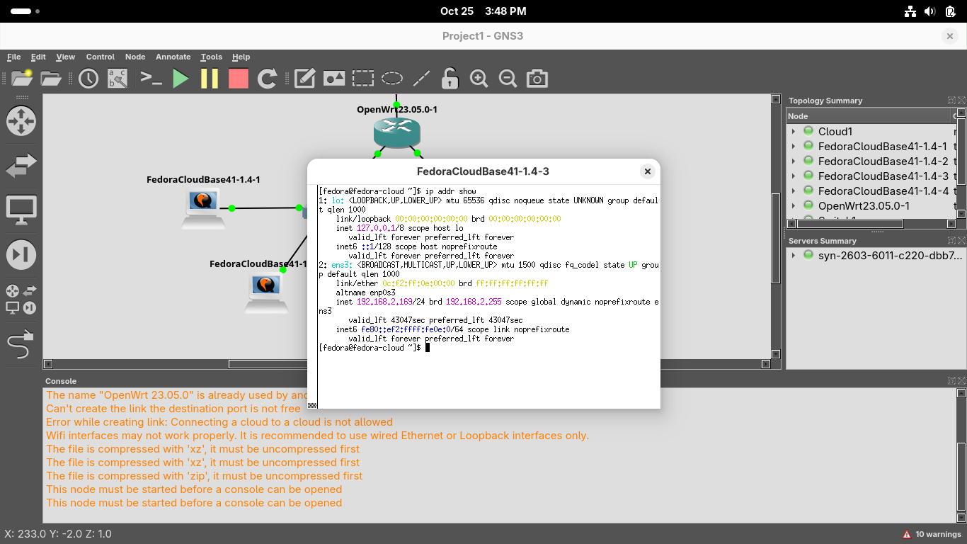
Close the Xterm window and right click the third workstation and run ip addr show from the console:

Close the Xterm window and right click the fourth workstation and run ip addr show from the console:
ip addr is a modern replacement for the older ifconfig command you will still see on older systems
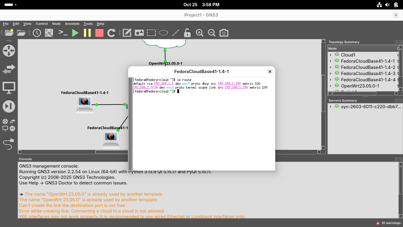
Head back to the first workstation and run the following command to find the default gateway:
[fedora@fedora-cloud ~]$ ip route
Resulting Output:
Close the Xterm window and right click the third workstation and run ip route from the console:

Notice that the systems have a different default gateway since they are on separate subnetworks
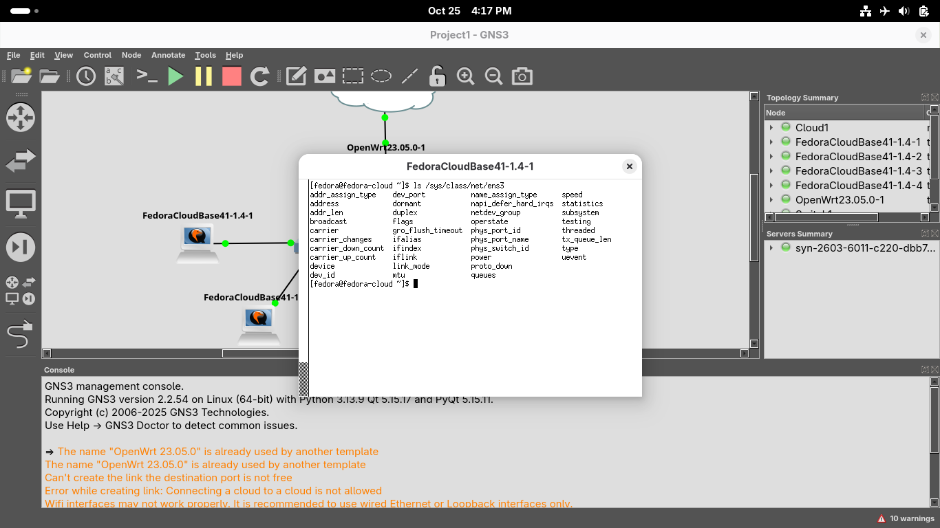
Head back to the first workstation and run the following command to display the configuration files:
[fedora@fedora-cloud ~]$ ls /sys/class/net/ens3
Resulting Output:
Run the following command from the Virtual Xterm Terminal to test default gateway connectivity:
[fedora@fedora-cloud ~]$ ping 192.168.1.1 -c 4
Resulting Output:

We can see from the that the packets we sent did receive a reply, indicating a working connection
If a host has a working IP Address, subnet mask and gateway, it can reach other hosts the router can
Run the following command from the Virtual Xterm Terminal to test connection between hosts 1 and 3:
[fedora@fedora-cloud ~]$ ping 192.168.2.196 -c 4
Resulting Output:

In the GNS3 topology window, right-click the Router and select Stop, you should see the links turn red
Head back into your Xterm window for workstation one and retry the ping 192.168.2.196 -c 4 command:
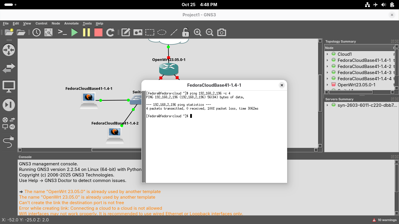
Without a default gateway, our system is unable to reach the hosts on the other segment of the network
In the GNS3 topology window, right-click the Touter and select Start, connectivity is now restored
12. Inspect ARP Caches
In this final section of the lab we will shift our focus to local subnet traffic and ARP mappings
The Address Resolution Protocol is used to map IP Addresses to Media Access Control Addresses locally
First, power down all of the devices and nodes on our network by clicking the Stop button at the top:
You will see the nodes turn red indicating a powered off state, turn them back on with start button:
Right click the first workstation and select the Console option to re-enter the Xterm Terminal
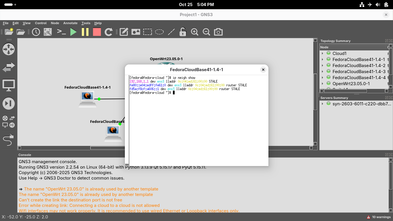
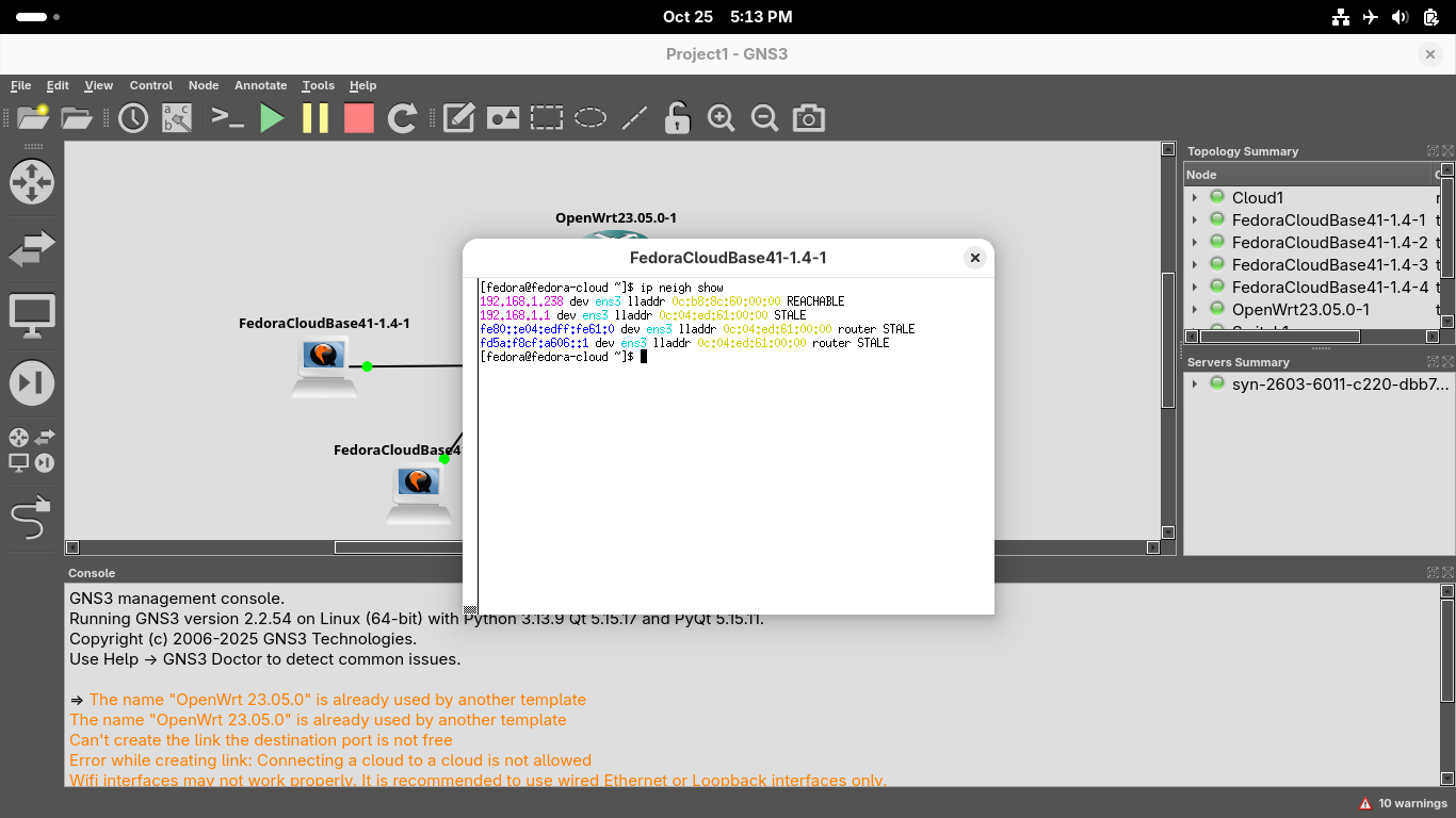
Run the following command from the Xterm Terminal window to view all cached ARP entries:
[fedora@fedora-cloud ~]$ ip show neigh
We have not made any networking requests yet, so there will be nothing displayed accept the gateway:
Run the following command from the Xterm Terminal window to test connectivity to local workstation2:
[fedora@fedora-cloud ~]$ ping 192.168.1.238 -c 4
Out first workstation will broadcast an ARP request to all hosts on the 192.168.1.0/24 subnetwork
Our second workstation will answer with its MAC address, which workstation1 will add to its ARP cache
Run the arp -a command on the first workstation Xterm Terminal window to view the updated ARP cache:
Run the ip addr show command from the first workstation Xterm Terminal to compare the MAC Addresses
Run the ping 192.168.2.196 -c 4 and arp -a commands from the first workstation Xterm Terminal:
We can see that nothing has changed, remember that ARP is only used to map MAC addresses locally
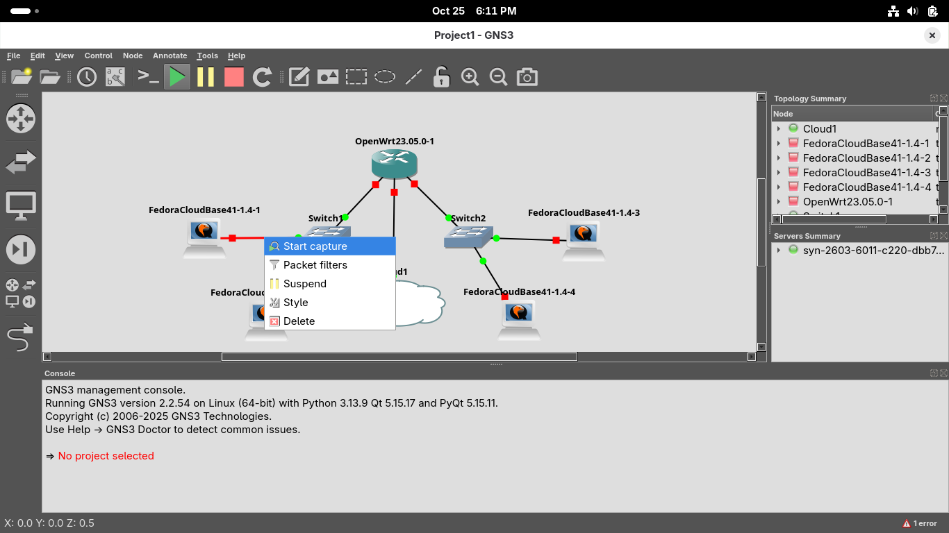
In the GNS3 topology window, use the Red Stop square at the top to stop all of the nodes and devices
Right click the link between our first workstation and the switch and select Start Capture, hit ok:
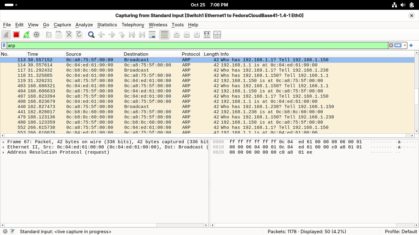
We are now capturing packets on the link, type 'arp' in the wireshark display filter field above:
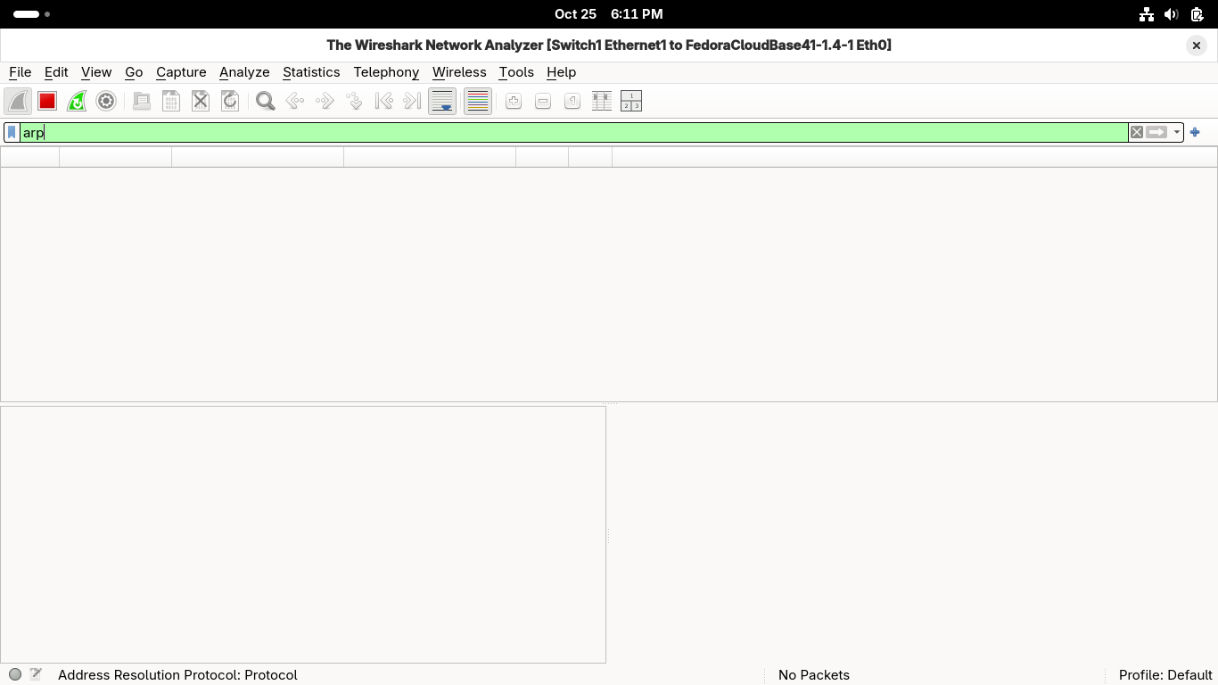
Now that we are filtering for ARP traffic, head back to GNS3 and restart all the nodes and devices
Open the console on our first workstation, run the ping 192.168.1.238 -c 4 command to create traffic
In Wireshark you should see that PC1 broadcasts a message and PC2 sends a reply with its MAC address:
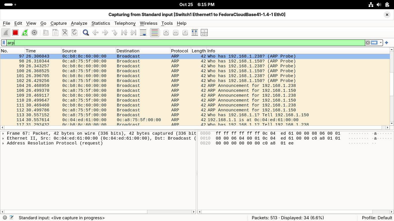
Run the ping 192.168.2.196 -c 4 command to create traffic targeting our second network segment:
We can see that the first workstation again sends a broadcast message looking for the MAC addresses
However this time rather than the target host, the router itself responds with its MAC address
Congratulations, you are now well equipped to simulate virtual networks and analyze their traffic
You've learned how to examine network configuration information on hosts, and text their connectivity
Lastly you've learned how to view ARP caches and how machines interact with one another ona a network