In this foundational lab, explore the essential hardware that powers modern computer networks. The focus is on identifying, configuring, and understanding the roles of key network devices including routers, switches, access points, and firewalls. Through hands-on exercises, you will gain practical experience in setting up and connecting basic network topologies and understanding MAC addresses, IP addressing, and packet forwarding.
Cybrary is a well established and free IT training platform with several intuitive labs to explore
A paid subscription with more advanced labs is available as well outside the scope of this platform
Head to https://www.cybrary.it to create a free account for learning available on their platform
Head to Network Device Basics to complete this lab for yourself or perform on your homelab below
Quick Links:
Requirements:
• Windows PC w/ Internet Connection
• USB Flash Drive w/ at least 8GB Capacity
• Second PC with at least 2 GB of memory and 2 CPU cores
1. Network Device Overview
Modern networking traces its roots to ARPANET, a prototype designed to connect research institutions
Initially, ARPANET employed proprietary, ad hoc methods for connectivity, this changed in the 1970's
This is when it adopted the TCP/IP protocol, establishing a standardized framework for communication
Early tools like Gopher and Usenet had limited functionality, making information retrieval challenging
The introduction of HTML and web browsers revolutionized access, allowing users to easily locate info
The implementation of DNS further simplified navigation by replacing IP Addresses with readable URLs
As the internet developed, organizations had begun creating networks using vendor specific protocols
Companies like IBM, Novell, and Sun Microsystems pioneered technologies for Local Area Networks (LAN)
Notable examples of these technologies include Arcnet, Token Ring, and the modern dominant Ethernet
Today, Ethernet over twisted-pair copper cables is the most widely adopted wired networking technology
Today speeds of 1 Gbps (1000Base-T) to the desktop are now both common to see and very cost-effective
Wireless networks have also evolved significantly, offering speeds ranging from 54 Mbps up to 100 Gbps
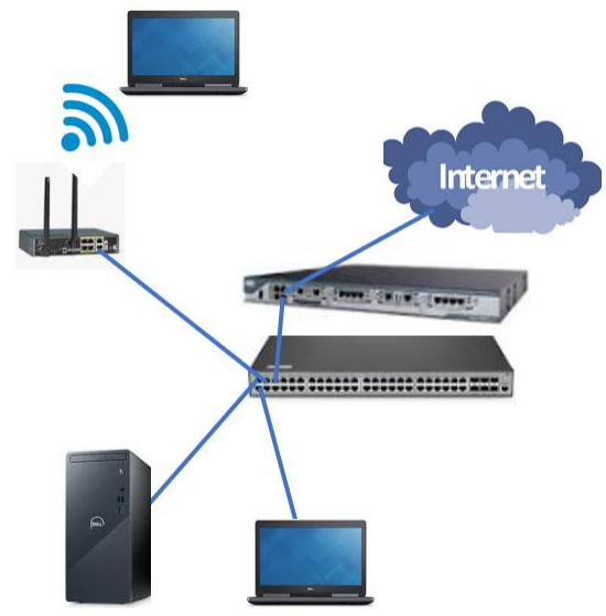
A network device is simply a device that facilitates local or wide-area communication between systems
What kinds of devices? The image below shows some of the common types of network devices in use today:
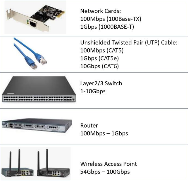
• The network interface card (NIC) connects servers and clients to the network
• An unshielded twisted pair (UTP) plugs directly into the NIC and the switch
• A switch is a layer 2 network device that manages local LAN traffic
• The router is a layer 3 device that can move traffic between LANS
• Wireless access points use a UTP cable to connect to a switch so wireless clients can join the LAN
The layers listed above refer to the layers of the OSI Network Reference model used as a framework
Switches operate at the Data Link Layer, and Routers operate at the Network Layer of the OSI model
There are also "Layer 3" switches that can manage both local LAN traffic and IP routing operations
Layer 3 switches can create isolated virtual LANs (VLANS) and route the network traffic between them:
Although you will rarely encounter them now, Legacy Network Devices commonly exist in older networks
• A hub is like a switch but instead of targeting specific destination addresses it blasts packets out to each device on the network
• A bridge is a network device that connects two LAN segments into a single LAN.
• Repeaters are used to extend the maximum physical length of cables
Here are some additional network devices that are commonly included in LANs for modern networks:
• A firewall controls the flow of traffic from a trusted to an untrusted area and vice-versa
• A proxy accesses content on behalf of a client, acting like a mediator between them
• A Virtual Private Network (VPN) allows clients outside the LAN to access LAN resources
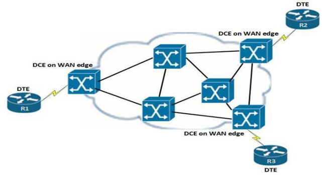
A Wide-Area Network (WAN) comprises hardware and protocols that uses connections over long distance
One example of this is Frame Relay, in which routers use serial cards to connect to other routers
Note that traffic over a WAN network is generally much slower than traffic over a local LAN network
2. Create Fedora Linux Live USB
Fedora is a popular Open-Source Linux distribution which is highly customizable and free to download
Maintained by the Fedora Project and originally a fork of Red Hat Linux, it aims to be the leading edge
You can use the operating system without having to install it onto your hard drive with a live USB
Download Fedora Workstation ISO: Fedora Official Download
Download Rufus Disk Imaging Tool: Rufus Official Download
Insert USB Flash Drive, run rufus.exe, select target drive, select Fedora Workstation ISO, Start:

Remove USB Flash Drive and Insert into second PC. Start PC and press hot boot key on startup:
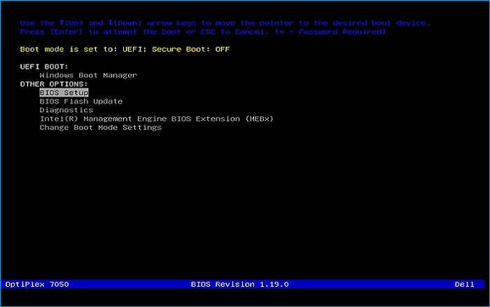
Select UEFI USB Flash Boot. Allow Fedora to load and scroll to select the Fedora Live option:

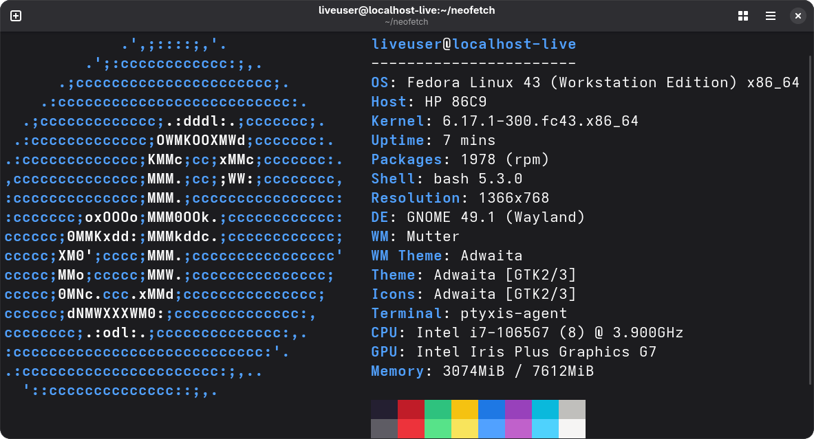
Now allow your workstation a moment to load and you will be taken to the Fedora Desktop Environment:
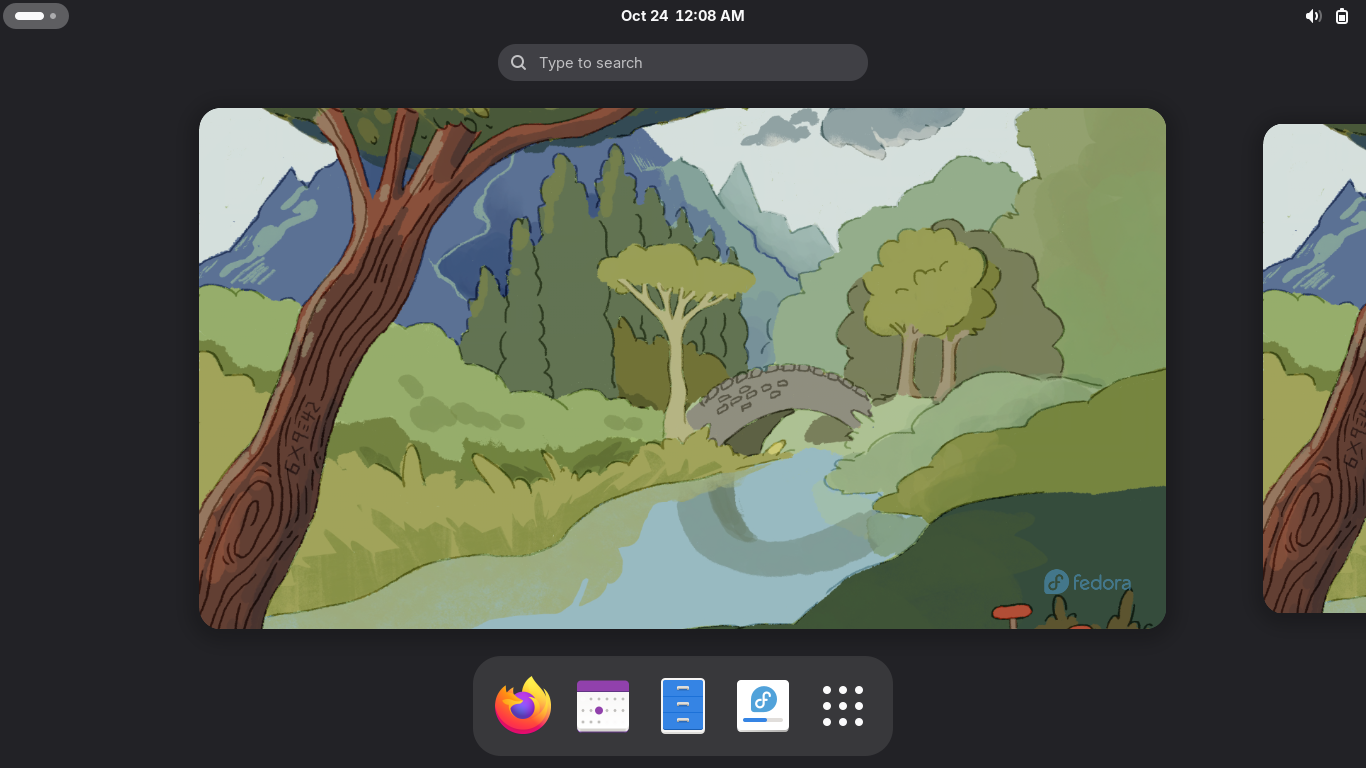
This live system won't save anything to your PC's hard drive and we will complete the lab here
For the GNS3 Application in the later sections of this lab to work properly, we need installation
3. Fedora Workstation Full-Install
From the Fedora Workstation Live Desktop, click the fourth icon at the bottom to begin installation
Choose your keyboard language from the installation menu and click next, select your disk below:
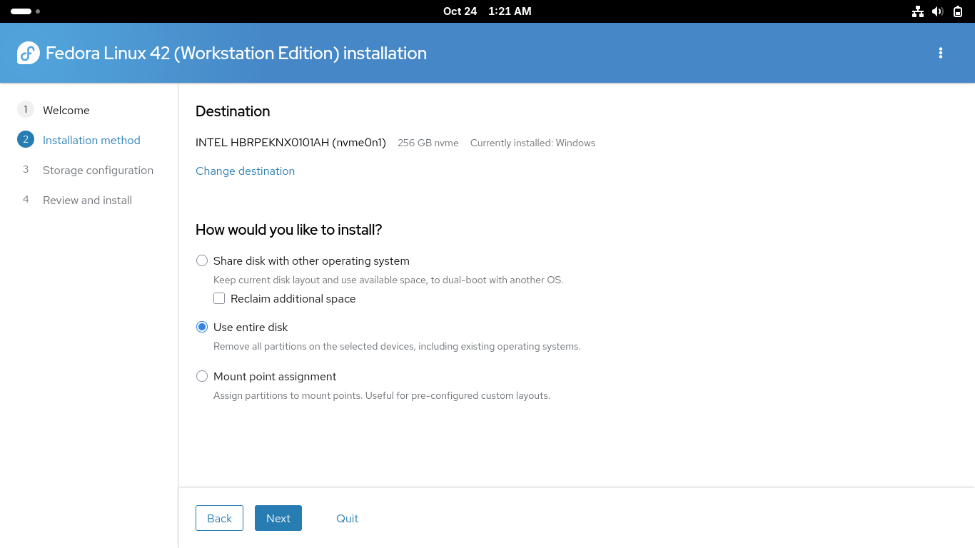
Make sure you select the option to use the entire disk above in order to allow Fedora enough space
Proceed by clicking next, for a quicker installation select not to encrypt the drive and hit next:
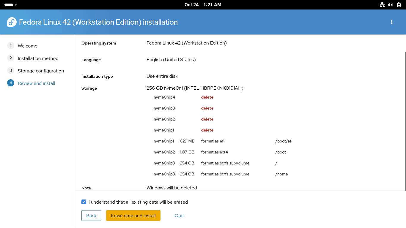
Click on the checkbox to confirm that all existing data will be erased, click erase data and install
This process will take some time, once completed reboot your PC to enter into your new fedora system
Once rebooted you will need to complete the first time setup including language, time zone and repo
You will also create your user account for the system. Make sure you enable third party repositories
4. Install GNS3 & Local VPCS Server
In this section you will practice analyzing a TCP/IP network topology using GNS3 network simulator
GNS3 is a free and open-source network emulation software that allows you to design and test networks
To get started with creating simulated network environments we must install the dependencies and GUI
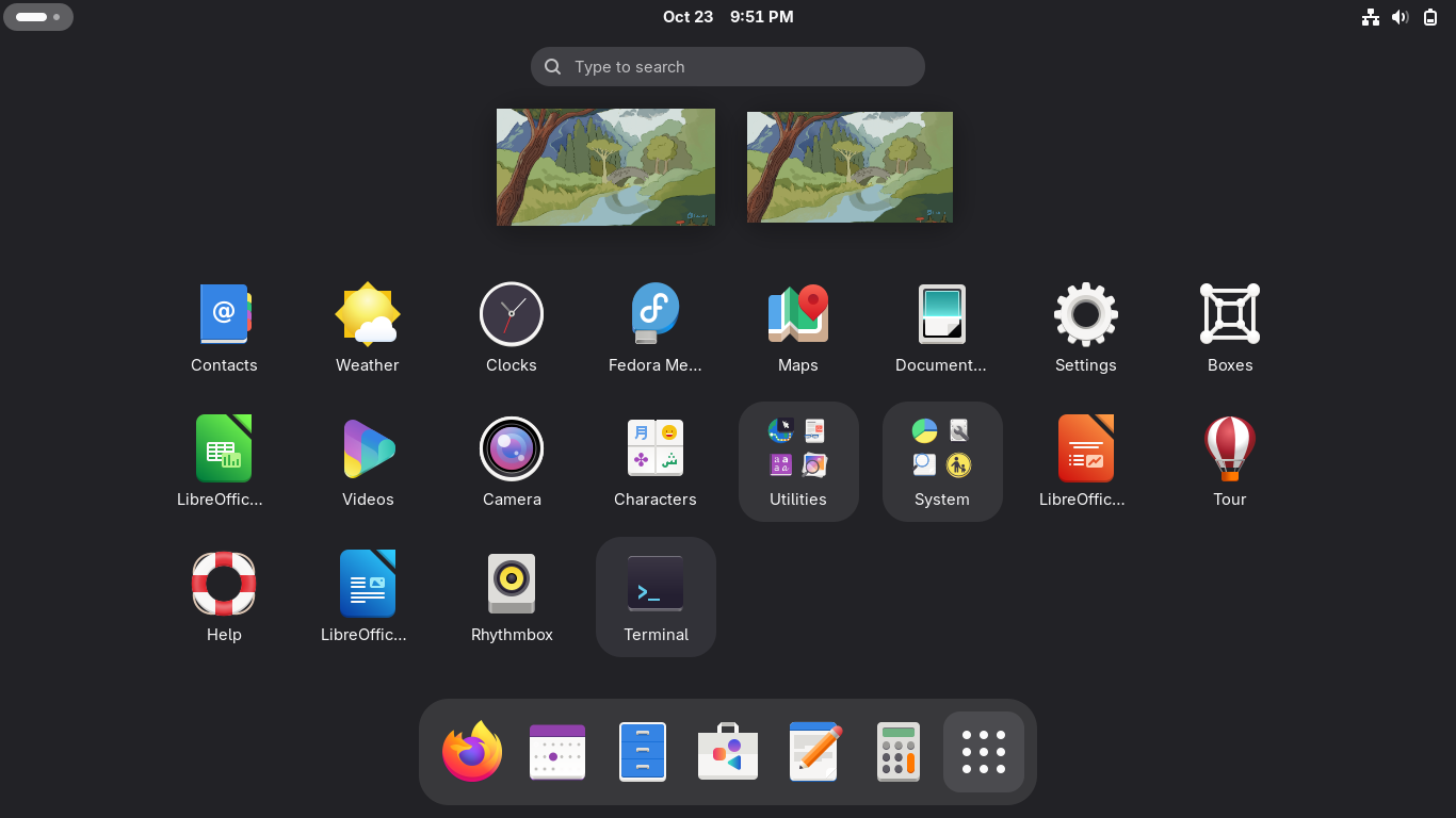
From the Fedora Desktop Environment click on the nine dots in the bottom right to view applications:
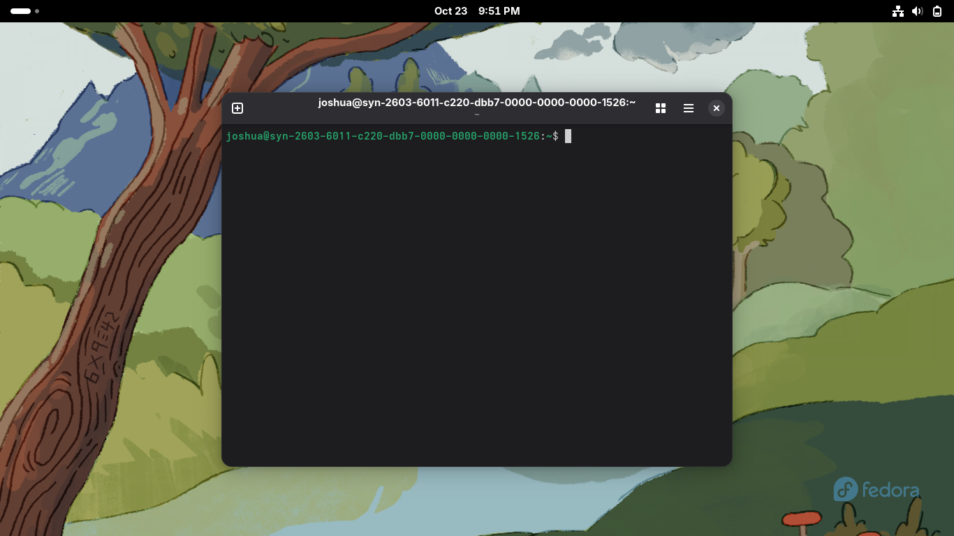
The Terminal is where we can execute CLI commands using the Bourne Again Shell scripting language:
Fedora uses the DNF package manager to install software and update system packages through commands
Run the following command from the Fedora Workstation Terminal to update all the available packages:
user@host:~$ sudo dnf -y upgrade --refresh
Run the following commands from the Fedora Workstation Terminal to install the GNS3 dependencies:
user@host:~$ sudo dnf -y install git gcc cmake flex bison
user@host:~$ sudo dnf -y install elfutils-libelf-devel libuuid-devel libpcap-devel
user@host:~$ sudo dnf -y install python3-tornado python3-netifaces python3-devel python-pip python3-setuptools python3-PyQt4 python3-zmq
GNS3 uses Wireshark for packet capturing and analysis functions. Ensure that Wireshark is installed
Run the following command from the Fedora Workstation Terminal to install the Wireshark Tool:
user@host:~$ sudo dnf -y install wireshark
Run the following command from the Fedora Workstation Terminal to install GNS3 server and GNS3 GUI:
user@host:~$ sudo dnf -y install gns3-server gns3-gui
VPCS is a Virtual PC Simulator which allows you to simulate DHCP and ping when using the GNS3 tool
The tool must be installed using an emulator utility called dynamips which can create custom binaries
Run the following commands from the Fedora Workstation Terminal to install the dynamips emulator:
user@host:~$ git clone https://github.com/GNS3/dynamips
user@host:~$ cd dynamips
user@host:~/dynamips$ mkdir build
user@host:~/dynamips$ cd build
user@host:~/dynamips/build$ cmake ..
user@host:~/dynamips/build$ sudo make install
Run the following commands from the Fedora Workstation Terminal to install the VPCS tool with dynamips:
user@host:~/dynamips/build$ wget https://liquidtelecom.dl.sourceforge.net/project/vpcs/0.8/vpcs_0.8b_Linux64
user@host:~/dynamips/build$ mv vpcs_0.8b_Linux64 vpcs
user@host:~/dynamips/build$ chmod +x vpcs
user@host:~/dynamips/build$ sudo cp vpcs /usr/local/bin/
We now have the GNS3 tool and the various dependencies and addons installed to our Fedora Workstation
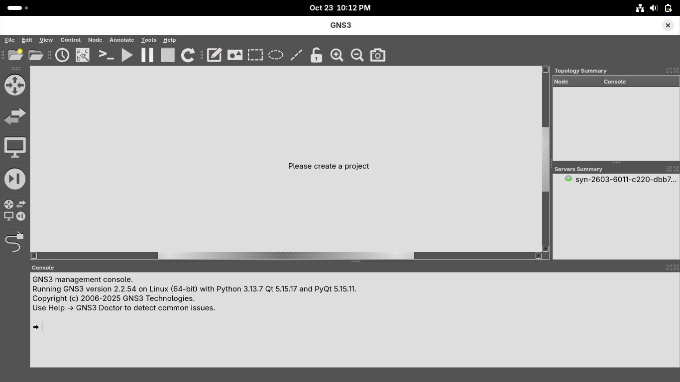
Run the following command from the Fedora Workstation Terminal to open GNS3 in the background:
user@host:~$ gns3 &

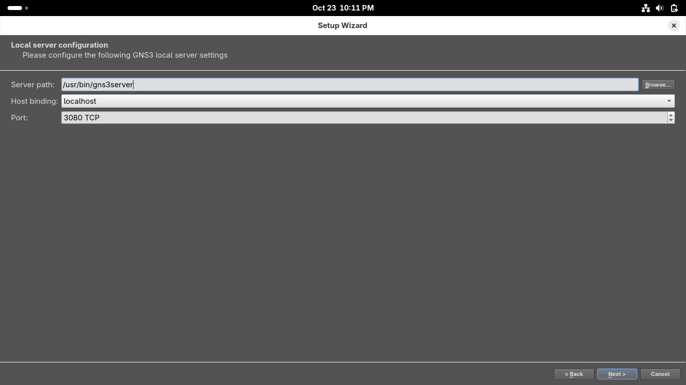
When GNS3 opens up you will be directed to the setup wizard, select 'Run the topologies on my computer'
On the second page use '/usr/bin/gns3server' as the local server path, use host 127.0.0.1 and port 3080:
On the configuration success page click next, then on the New appliance template page click on finish:
We now have full network emulation along with a virtual PC simulator to create virtual machines for us
5. Install KVM Hypervisor, Xterm & TigerVNC Viewer
In order for us to use KVM and QEMU virtual machines inside GNS3 we the to install the KVM Hypervisor
Run the following command from the Fedora Workstation Terminal to check if your CPU supports VMs:
user@host:~/dynamips/build$ cat /proc/cpuinfo | egrep "vmx|svm"
If your see the terms vmx or svm appear anywhere in the output of the previous command you are good
Run the following commands from the Fedora Workstation Terminal to install the KVM / QEMU packages:
user@host:~/dynamips/build$ sudo dnf -y install bridge-utils libvirt virt-install qemu-kvm
user@host:~/dynamips/build$ sudo dnf -y install libvirt-devel virt-top libguestfs-tools guestfs-tools
Run the following commands from the Fedora Workstation Terminal to start and enable the KVM daemon:
user@host:~/dynamips/build$ sudo systemctl start libvirtd
user@host:~/dynamips/build$ sudo systemctl enable libvirtd
Run the following commands from the Fedora Workstation Terminal to install the Xterm VM Manager:
user@host:~/dynamips/build$ sudo dnf -y install virt-manager
user@host:~/dynamips/build$ sudo dnf -y install xterm
Run the following command from the Fedora Workstation Terminal to install the TigerVNC viewer:
user@host:~/dynamips/build$ sudo dnf -y install vncviewer
Now we are clear to proceed with the lab and have the ability to use our virtual Fedora Workstations
6. Create a Virtual Network Environment
To begin our analysis of networking topology we must first create the environment we will be analyzing
From the GNS3 GUI window click on File > New Blank Project > title your project as Project1 and hit ok:

We must import appliances in order to simulate them on our environment, head to File > New Template

Install an appliance from the GNS3 server > Firewalls > pfSense > Install the appliance on local computer
Click next and choose the /usr/bin/qemu-system-x86_64 (v9.2.4) Qemu Binary > Click Next > pfSense v2.7.2
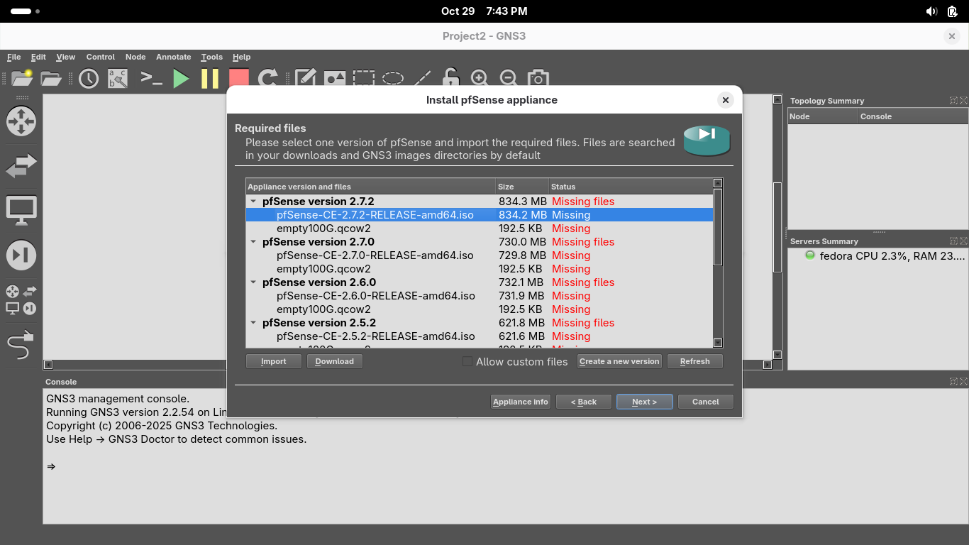
Click on image file displayed as missing, you can find the repository at pfSense Image Repository
Run the following command from the Fedora Workstation Terminal to unzip our pfSense image file:
user@host:~/ gunzip ~/Downloads/pfSense-CE-2.7.2-RELEASE-amd64.iso.gz
You can download the additional file by clicking on it in GNS3 and clicking on the Download button below
Now select the image file and qcow2 files and import them from your downloads folder, then install it:
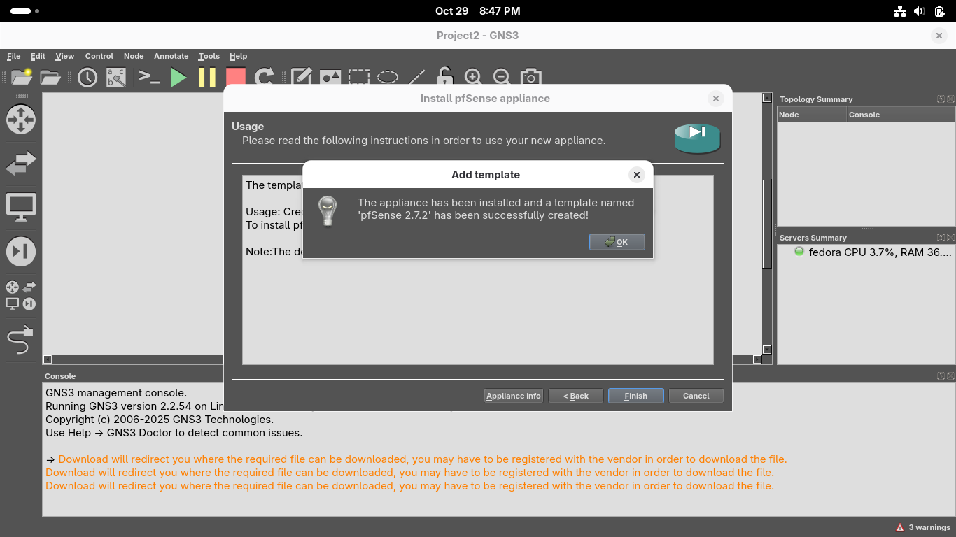
From GNS3 GUI Window head to File > New Template > Install an appliance from the GNS3 server > Routers
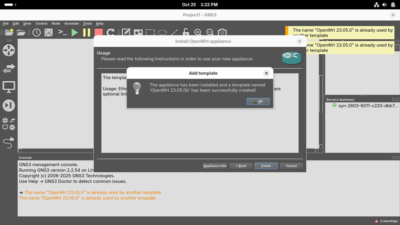
Install an appliance from the GNS3 server > OpenWRT > Install > Install the appliance on local computer:
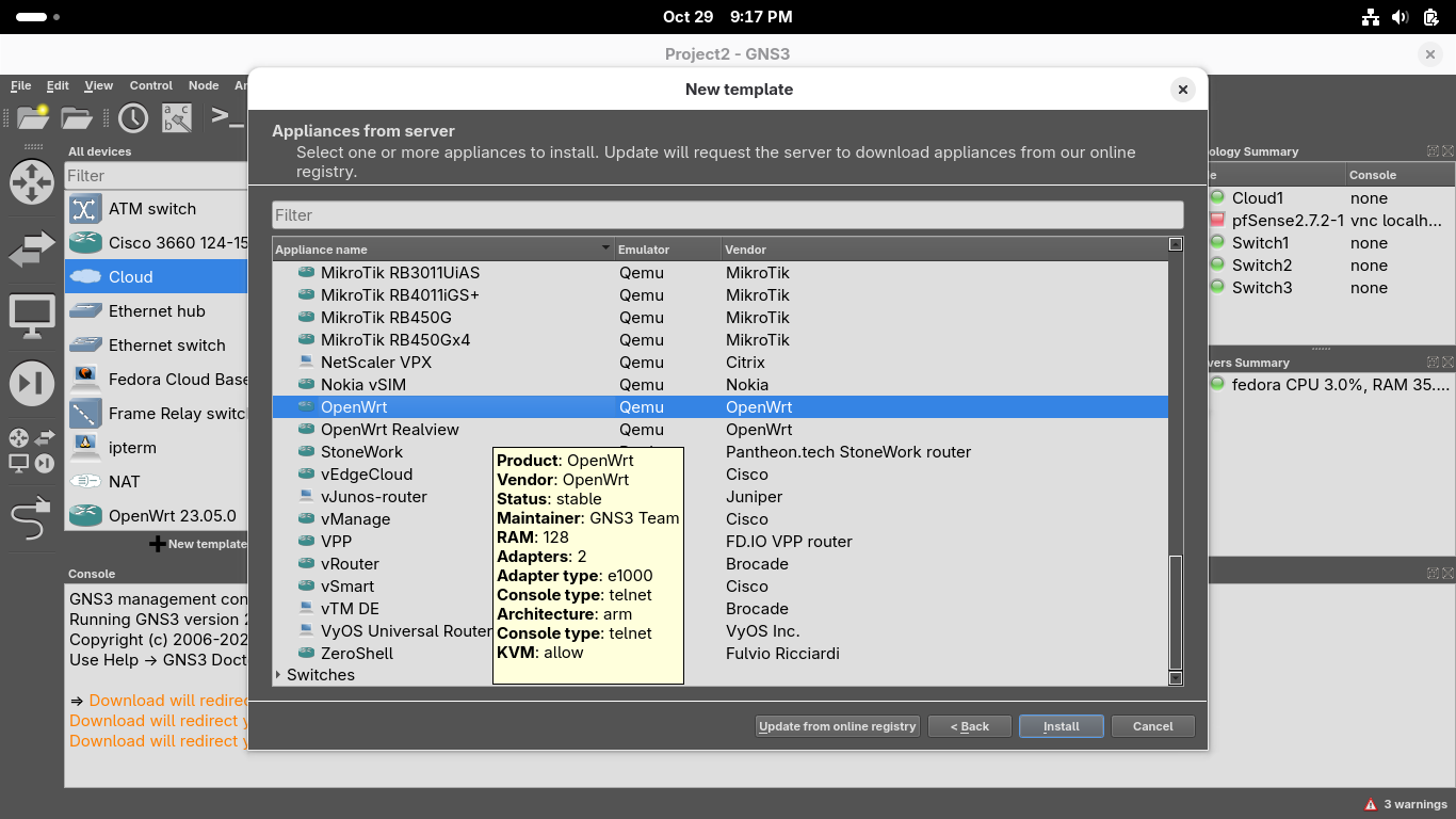
Click next and choose the /usr/bin/qemu-system-x86_64 (v9.2.4) Qemu Binary > Click Next > OpenWRT 23.05.0:

Click on image file displayed as missing and click on Download to be taken to your browser to download
Once downloaded head back into GNS3 and click refresh and proceed to install the OpenWRT router appliance
We will now add some virtual systems to act as hosts on our network on which we can get remote shells
From GNS3 GUI Window head to File > New Template > Install an appliance from the GNS3 server > Guests:

Navigate to select the Fedora Cloud Base guest, install > Install the appliance on your local computer
From the Install Fedora Cloud Base appliance menu, select the /usr/bin/qemu-system-x86_64 binary option
Click on the two lines underneath Fedora Cloud Base version 41-1.4 and click on Download for each one:
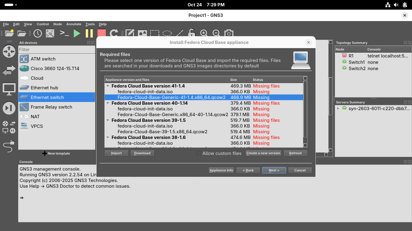
The Download button will take you to a link in your systems default browser firefox to download these
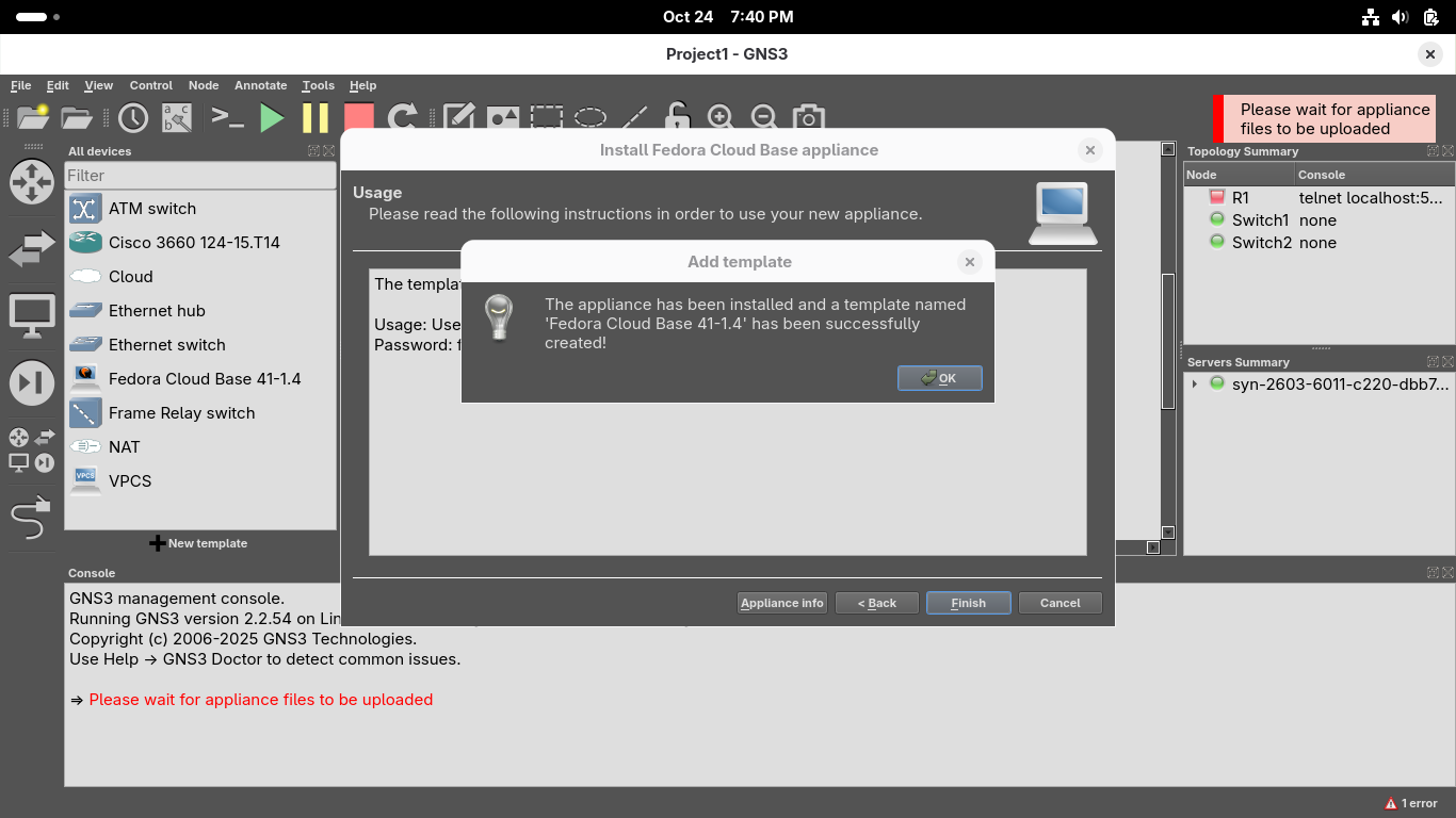
Once the download for each of these files has completed, close your browser and hit refresh in GNS3:
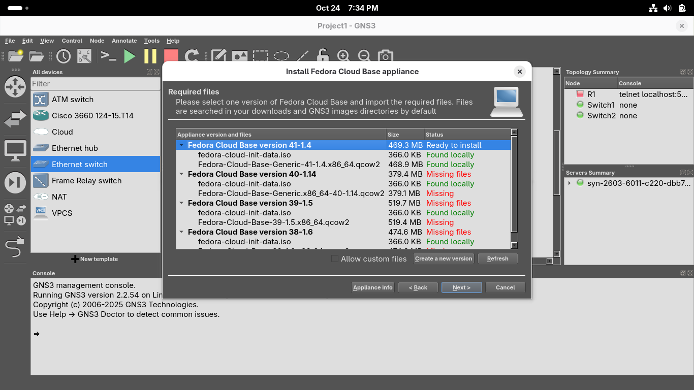
Click next and confirm you'd like to install the appliance, once installed click finish from the menu:
Lastly we will import an agent which will allow us to use the pfSense web GUI configuration utility
From GNS3 GUI Window head to File > New Template > Install an appliance from the GNS3 server > Guests:

Navigate to select the Firefox guest, install > Install the appliance on your local computer option
From the Install Firefox guest appliance menu, select the /usr/bin/qemu-system-x86_64 binary option
Click on the line underneath Firefox Guest version 31.1.1~2 and click on the Download option:
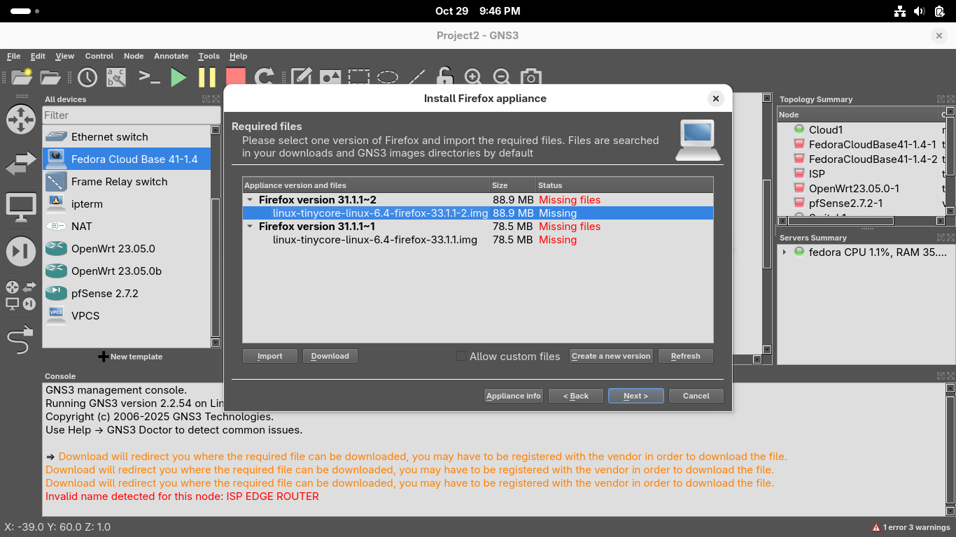
The Download button will take you to a link in your systems default browser firefox to download this
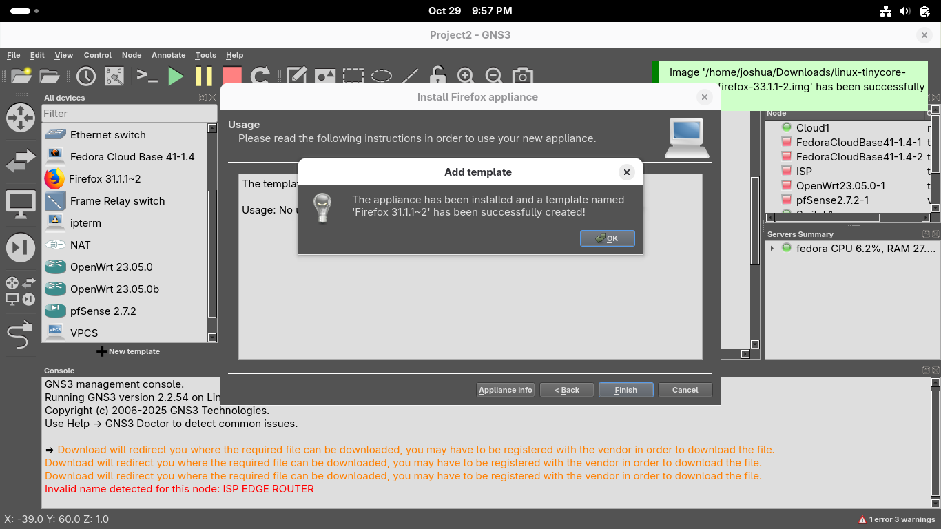
Once the download for the image file has completed, close your browser and hit refresh in GNS3:
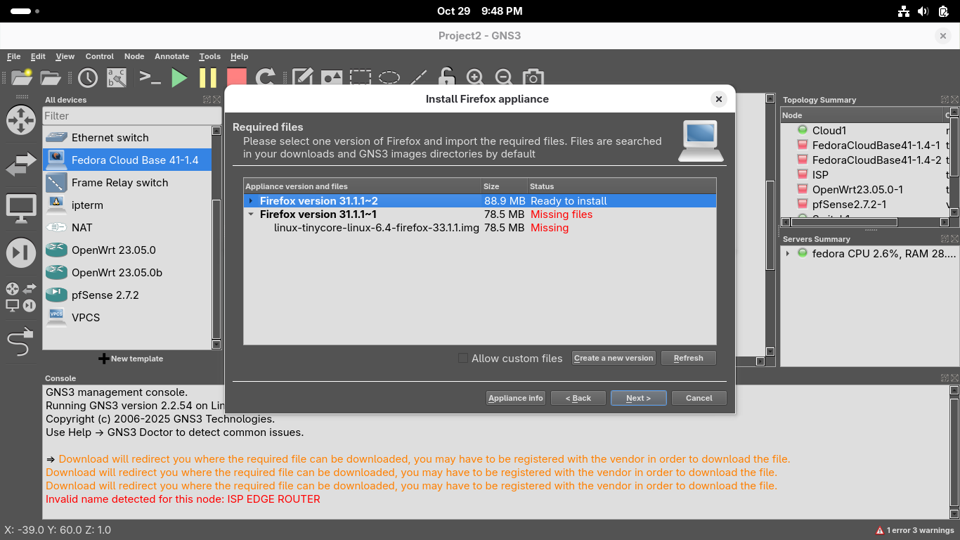
Click next and confirm you'd like to install the appliance, once installed click finish from the menu:
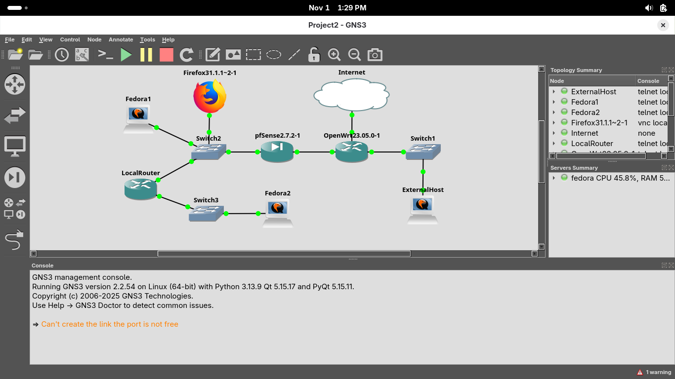
Now select the Browse all devices option on the left and drag and drop our devices into this topology:
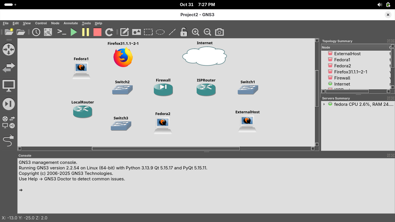
Use the wire icon on the left of the GNS3 GUI window to create links between the devices like below
On the Firewall device, em1 is the LAN interface and connects to the left switch, em0 to the right router
On the ISPRouter device, the WAN interface is eth1 and should connect to the cloud, eth0 and eth2 to other
On the LocalRouter device, use the eth1 interface to connect to switch2 and eth1 to connect to switch3:

Our virtual network environment is now primed and ready to go for the next few sections of our exercise
7. Configure the ISP Router
In order for our ISP Router to have it's own IP address and separate network we can edit the configuration
Right click on the device and select the green start button, when the connections turn green hit console

Run the following commands from the OpenWRT Console to add the lan2 interface and change the devices IP:
root@OpenWrt:/# uci set network.lan.ipaddr='66.67.68.1'
root@OpenWrt:/# uci set network.lan2=interface
root@OpenWrt:/# uci set network.lan2.proto='static'
root@OpenWrt:/# uci set network.lan2.ipaddr='100.200.100.1'
root@OpenWrt:/# uci set network.lan2.netmask='255.255.255.0'
root@OpenWrt:/# uci set network.lan2.device='eth2'
root@OpenWrt:/# uci set network.lan2.ip6assign='60'
Run the following commands from the OpenWRT console to add DHCP support for our lan 2 interface:
root@OpenWrt:/# uci set dhcp.lan2=dhcp
root@OpenWrt:/# uci set dhcp.lan2.interface='lan2'
root@OpenWrt:/# uci set dhcp.lan2.start='100'
root@OpenWrt:/# uci set dhcp.lan2.limit='150'
root@OpenWrt:/# uci set dhcp.lan2.leasetime='12h'
Run the following commands from the OpenWRT console to create a firewall zone for our lan 2 interface:
root@OpenWrt:/# uci add firewall zone
root@OpenWrt:/# uci set firewall.@zone[-1].name='lan2'
root@OpenWrt:/# uci set firewall.@zone[-1].network='lan2'
root@OpenWrt:/# uci set firewall.@zone[-1].input='ACCEPT'
root@OpenWrt:/# uci set firewall.@zone[-1].output='ACCEPT'
root@OpenWrt:/# uci set firewall.@zone[-1].forward='REJECT'
root@OpenWrt:/# uci add firewall forwarding
root@OpenWrt:/# uci set firewall.@forwarding[-1].src='lan2'
root@OpenWrt:/# uci set firewall.@forwarding[-1].dest='wan'
Run the following command from the OpenWrt console to commit the uci changes and restart the network:
root@OpenWrt:/# uci commit
root@OpenWrt:/# /etc/init.d/network restart
root@OpenWrt:/# /etc/init.d/dnsmasq restart
root@OpenWrt:/# /etc/init.d/firewall restart
Run the following commands from the OpenWrt console to enable forwarding between the subnetworks:
root@OpenWrt:/# uci add firewall forwarding
root@OpenWrt:/# uci set firewall.@forwarding[-1].src='lan'
root@OpenWrt:/# uci set firewall.@forwarding[-1].dest='lan2'
root@OpenWrt:/# uci commit
root@OpenWrt:/# /etc/init.d/firewall restart
root@OpenWrt:/# uci add firewall forwarding
root@OpenWrt:/# uci set firewall.@forwarding[-1].src='lan2'
root@OpenWrt:/# uci set firewall.@forwarding[-1].dest='lan'
root@OpenWrt:/# uci commit
root@OpenWrt:/# /etc/init.d/firewall restart
Now we have configured the ISP network to enable connectivity on the external device connected to eth2
8. Examine the Firewall Device
In this section of our lab, you will examine the pfSense device and how it functions in the topology
The pfSense firewall device is a multi-purpose network appliance providing firewall, router and DHCP
In this topology, the pfSense firewall device functions as the LAN's primary router and default gateway
To get started, right-click the pfSense firewall device and select the start option to power it online:
When the network interfaces turn green, right-click the pfSense firewall and select the Console option:
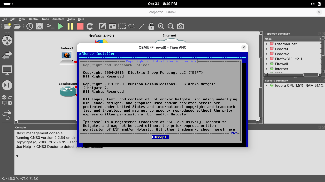
Press Enter a few times until you are prompted to select the disk, press space to select the disk below:

Now press enter to proceed, when prompted if we want to destroy disk contents, press tab to select yes:
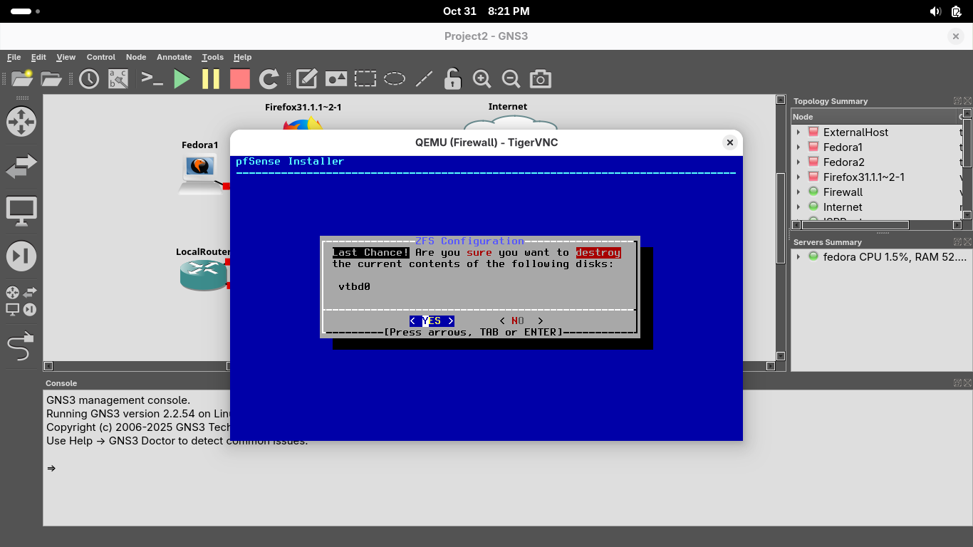
This may take some time, but once the installation is complete you will be prompted to reboot, enter:
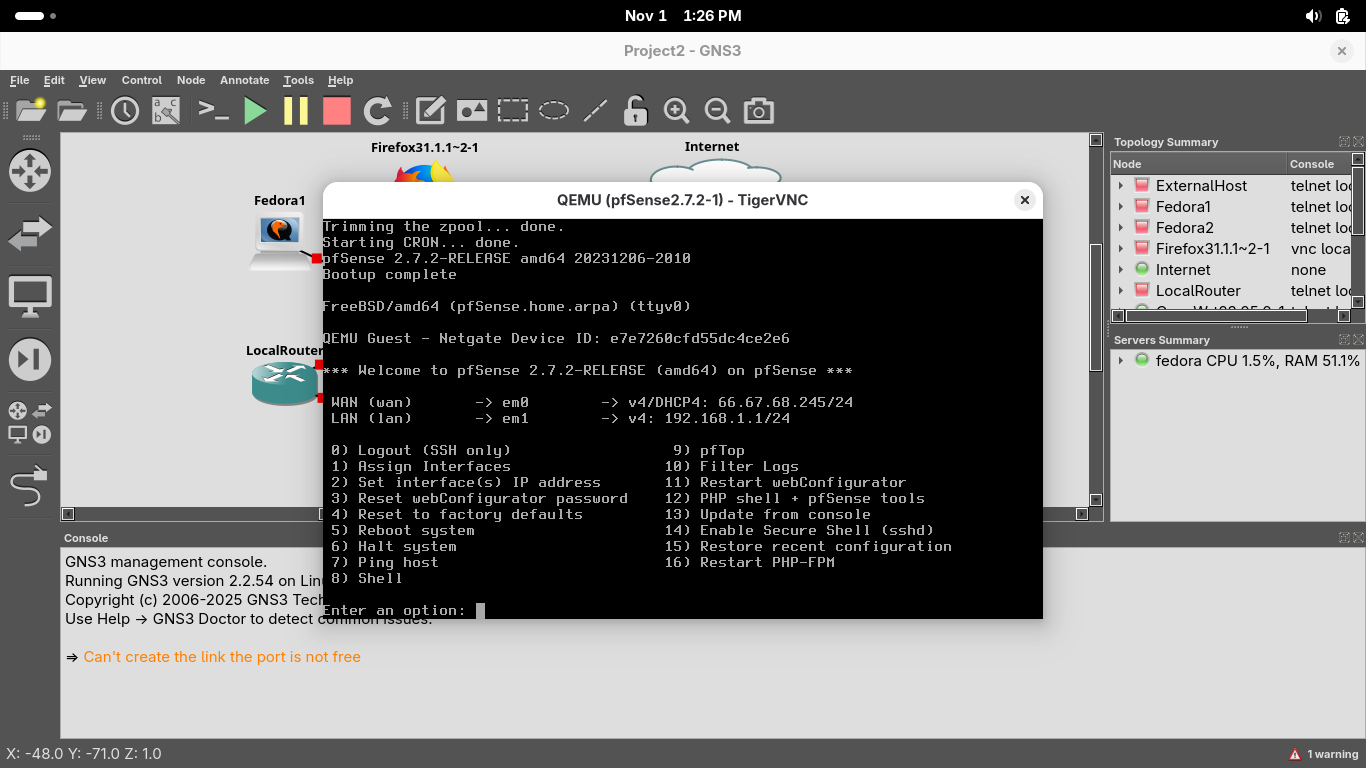
Our firewall appliance has been installed, close the VNC window and click start to power on the devices:
In the GNS3 topology window, you will see all connections turn green, indicating that connectivity is on
In the topology window, right-click the firefox host and select Console to open a VNC console connection
TigerVNC will open a Firefox. We will use the browser to interface with the pfSense appliances web GUI
Although you could interact with the pfSense appliance directly through the command line, this is easier
In the web browser, type '192.168.1.1' into the URL bar and press enter to connect to the pfSense GUI
We can see a security warning appear, this is because the appliance self signs it's SSL/TLS certificate
To enter the web GUI click on 'I Understand the Risks' > 'Add Exception' > 'Confirm Security Exception':
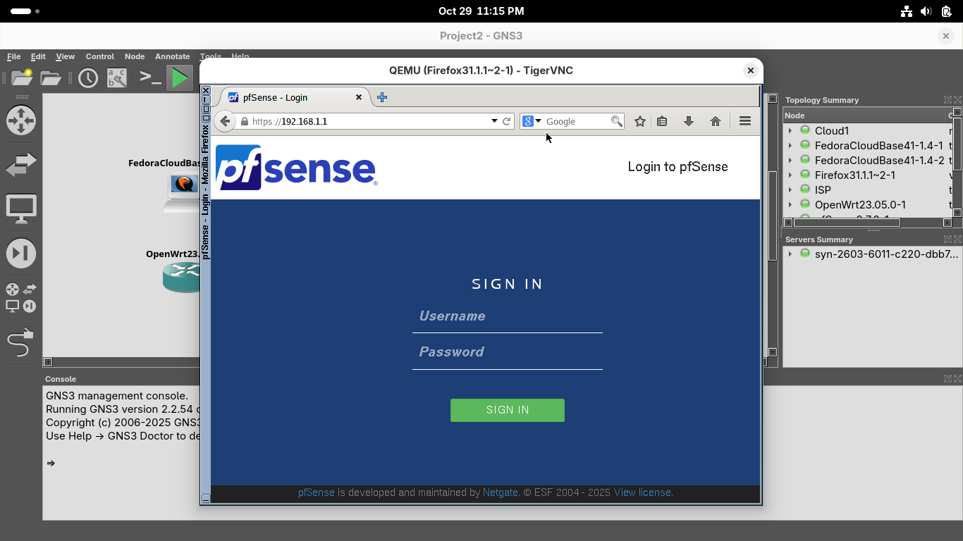
Let's sign in with the default credentials which are username: admin, password: pfsense, click sign in:
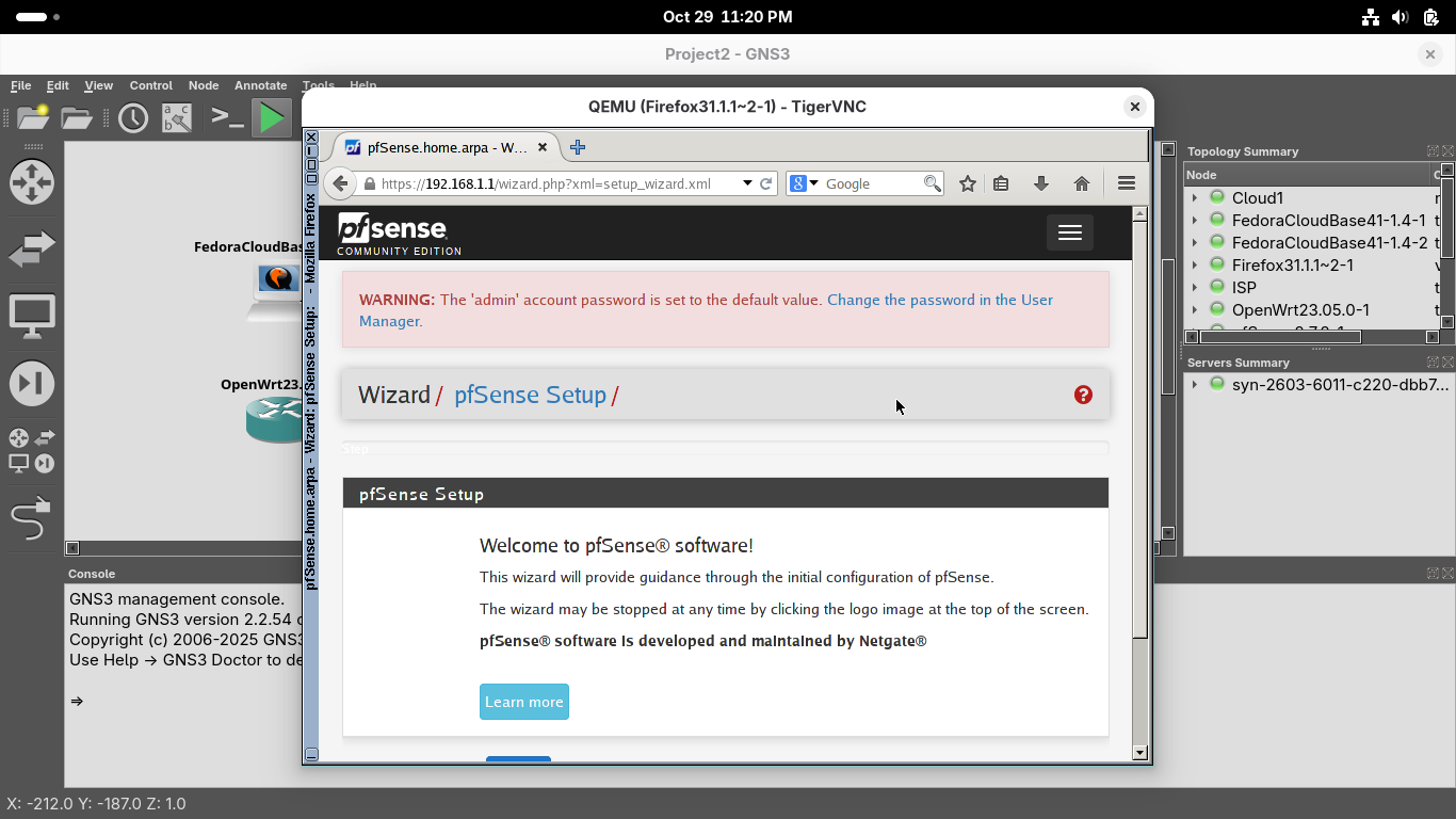
Scroll down to select next and complete the web GUI first time setup with the following network options:
• Hostname: pfSense
• Domain: home.arpa
• Primary DNS Server: 1.1.1.1
• Secondary DNS Server: 8.8.8.8
• Override DNS: Keep Checked
Continue with the default options until you reach the Configure WAN Interface page, select options below:
• SelectedType: Static
• IP Address: 66.67.68.2
• Subnet Mask: 24
• Upstream Gateway: 66.67.68.1
All other configuration settings can remain unchanged, the system will also make you create a password
It will also prompt you to perform a reload for the changes to take affect, click finish once complete:
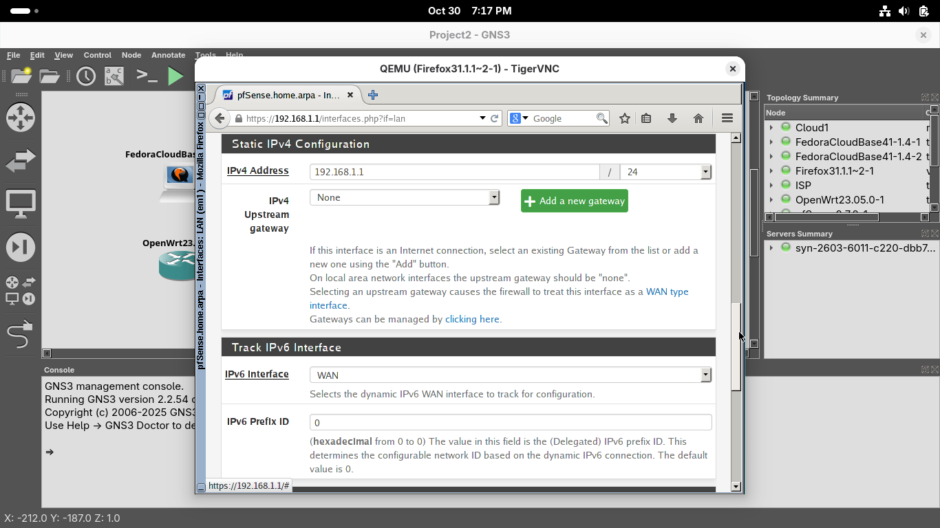
Click the three lines at the top and head to Interfaces, then select LAN to open the em1 LAN interface
On the interfaces / LAN configuration page, scroll down to Static IPv4 to see the firewall's internal IP:
From the menu at the top click Interfaces and select WAN to open the em0 WAN interface configuration page
On the interfaces / WAN configuration page, scroll down to Static IPv4 to see the firewall's external IP:
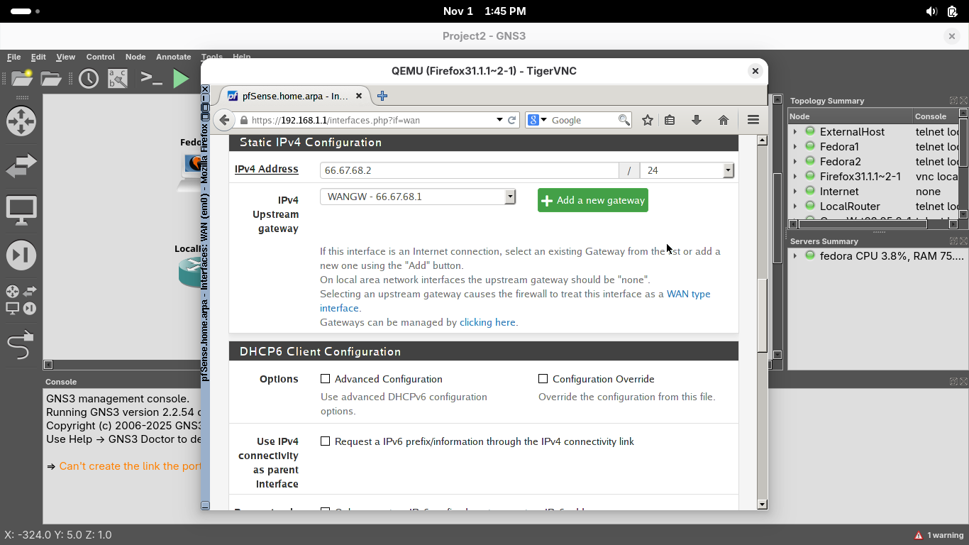
Take note of the IPv4 Upstream Gateway. The firewall will pass all non-local traffic to this ISP device
This simulated LAN connects to the "Internet" using an Internet Service Provider (ISP) which enables it
The ISP's job is to route traffic to and from the internet on behalf of the firewall which acts as the edge
Now let's test the connection to the ISP, from the top menu head to Diagnostics and select the Ping option
On the diagnostics / Ping page, type 66.67.68.1 in the Hostname field, then click ping to test connection:

We can see a positive ping test result at the bottom, indicating a working network connection to the ISP
9. Examine the DHCP Server & Host Network Configurations
Now we will switch gears and examine the process which enables devices to get IP Addresses, called DHCP
DHCP stands for Dynamic Host Configuration Protocol and grants clients an IP Address from a defined pool
Hosts on the LAN configured to use DHCP will automatically be assigned an IP Address when they boot up
From the menu bar at the top, click Services and select the DHCP Server option to view the configuration
We can see on the Services / DHCP Server / LAN page that the DHCP is enabled, allocated IP's to devices
Scroll down to see the Range of IP Addresses, this DHCP server will provide addresses from .10 to .245:
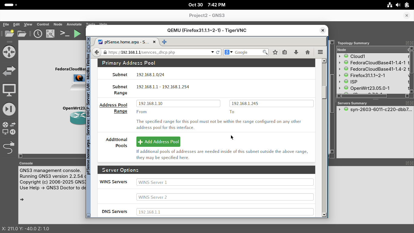
Scroll down further and note that clients are also sent the firewall's internal LAN address as the gateway
Minimize the TigerVNC console window, in the GNS3 topology menu, right-click Fedora 1 and select console:

You can log in to the system with the default credentials which are username: fedora, password: fedora
Run the following commands from the Fedora Workstation Terminal to display the live network configuration:
[fedora@fedora-cloud ~]$ ip addr show
[fedora@fedora-cloud ~]$ ip route
Resulting Output:

Notice that this device indeed has an assigned IP Address from the address pool on the the firewall device
Switch to the TigerVNC console with Firefox, Click on the terminal icon located at the bottom of window
Run the following commands from the LXTerminal Window to confirm the connectivity of the Firefox host:
gns3@box:~$ cat /etc/resolv.conf
gns3@box:~$ ifconfig
gns3@box:~$ netstat -rn
Resulting Output:
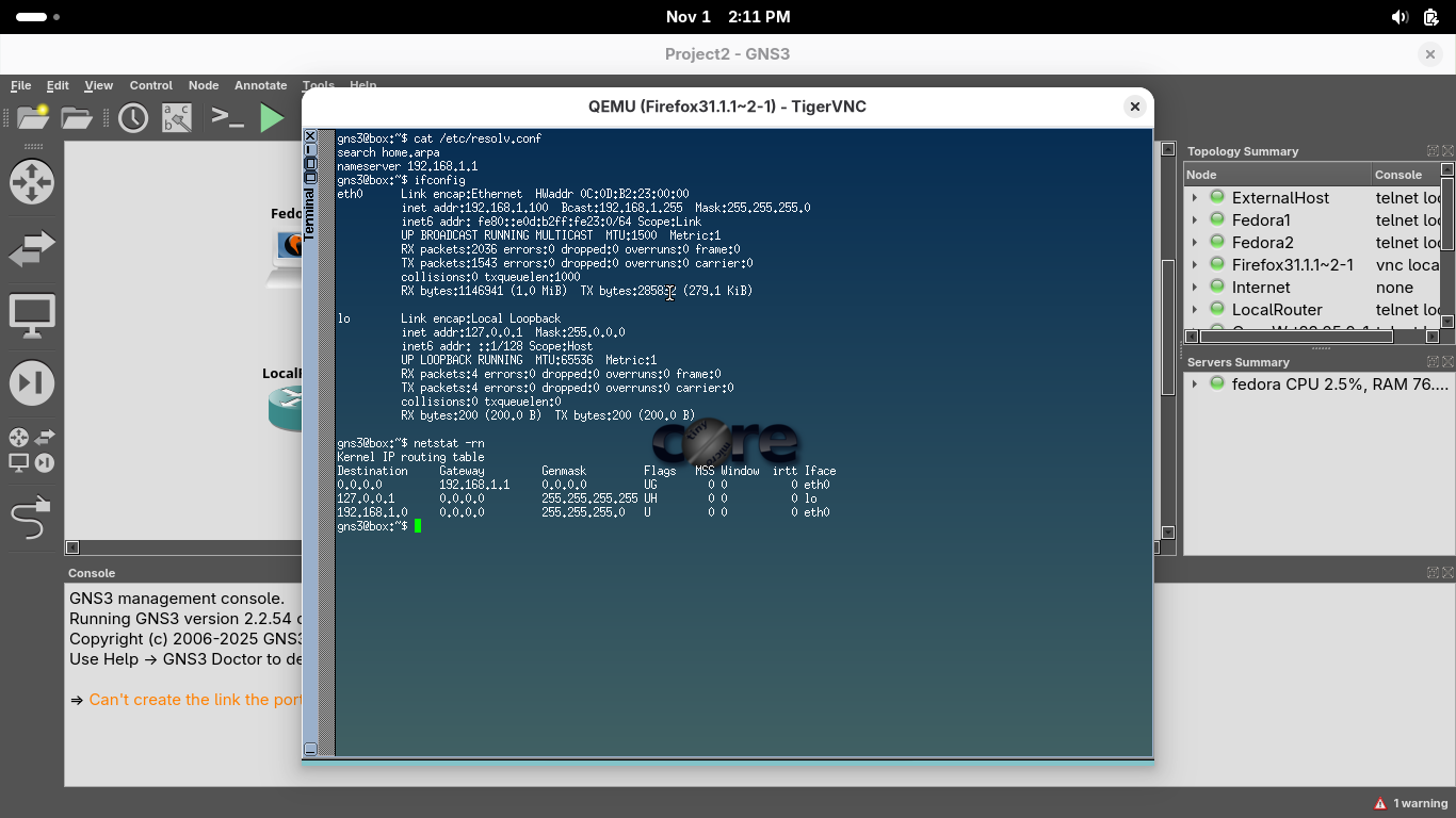
The 0.0.0.0 means "everything". Thus we are sending "everything" not local to the networks default gateway
We can see from the output that DHCP has also provided the firefox host an IP Address and default gateway
Go ahead and close the LXTerminal window, but leave the web browser inside the TigerVNC console opened
10. Examine the Firewall Rules
In this part of the lab you will examine the pfSense appliances firewall feature by reviewing the rules
In the TigerVNC console, scroll up to the menu bar at the top in the web browser, click Firewall > Rules:
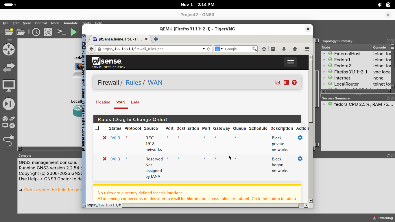
Notice there are no rules configured for the WAN firewall interface, although not visible, deny all exists
pfSense is a stateful firewall, it knows when a valid request is made from internal client to allow to pass
As such, traffic that is in reply to a valid request (made from an internal client) is allowed to pass by
Click on the LAN tab, you should see three firewall rules in effect on the Firewall / Rules / LAN page:
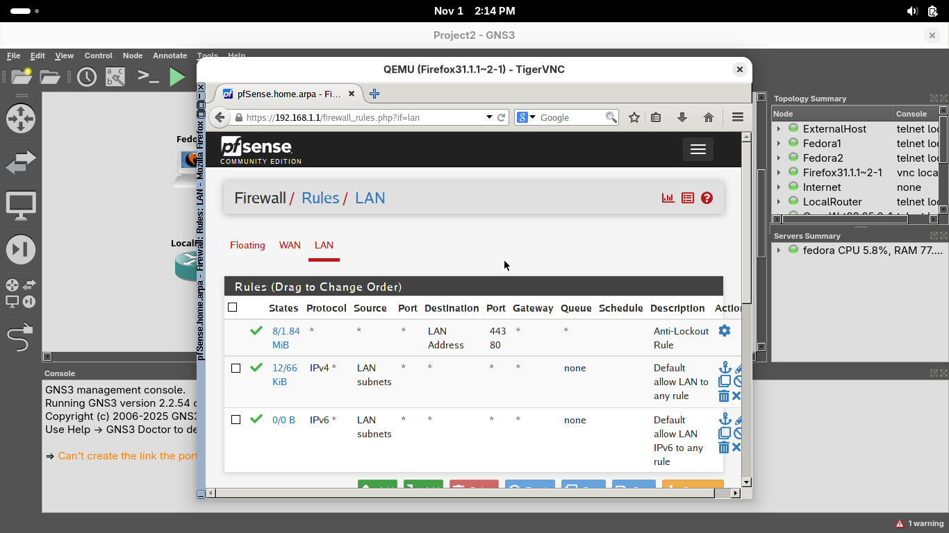
The first rule ensures we can connect to the firewall's web configuration page from a browser on port 80
The second rule allows all IPv4 traffic from the LAN network to any destination to pass through freely
The third rule allows all IPv6 traffic from the LAN network to any destination to pass through freely
While this default firewall configuration is fine for a lab, a production firewall should limit this
This current ruleset means that clients on the LAN should be able to reach anything on the 'Internet'
Let's test this right-click on our ExternalHost and select the console option, login with fedora/fedora
Run the following commands from the external workstation terminal to view the live network configuration:
[fedora@fedora-cloud ~]$ ip addr show
[fedora@fedora-cloud ~]$ ip route
Resulting Output:

We can see the devices IP Address, switch to the Fedora1 workstation and right-click and select console
Run the following command from the Fedora1 Workstation Terminal to ping the external web device:
[fedora@fedora-cloud ~]$ ping 100.200.100.113 -c 4
Resulting Output:

We can see that our firewall appliances rules table allowed the traffic from the LAN to pass to the WAN
Switch back to the ExternalHost device by right-clicking on it and selecting the console menu option
Run the following command from the ExternalHost Console to ping the ISPRouter and Firewalls WAN:
[fedora@fedora-cloud ~]$ ping 66.67.68.1 -c 4
[fedora@fedora-cloud ~]$ ping 66.67.68.2 -c 4
Resulting Output:

We can see the packets can reach our ISPRouter but the traffic is treated is dropped by our firewall
11. Configure a New Subnet
Next we will focus on the internal router and the second fedora workstation located within our local LAN
In the next steps, we will configure the Router to accommodate a new network subnet that serves fedora 2
Our second subnet is 10.10.10.1/24. The router will need two NICs for the new subnet and 192.168.1.0/24
In the GNS3 topology window, right-click the Router device and select the Console option from the menu:

Run the following command from the OpenWRT Console to change the internal subnets IP Addressing pool:
root@OpenWrt:/# uci set network.lan.ipaddr='10.10.10.1'
root@OpenWrt:/# uci commit
root@OpenWrt:/# /etc/init.d/network restart
Run the following command from the OpenWRT Console to test the change was successful by viewing the IP:
root@openwrt:~$ ip addr show
Resulting Output:

Run the following command from the OpenWRT Console to check the default gateway for the subnetwork:
root@openwrt:~$ ip route
Resulting Output:

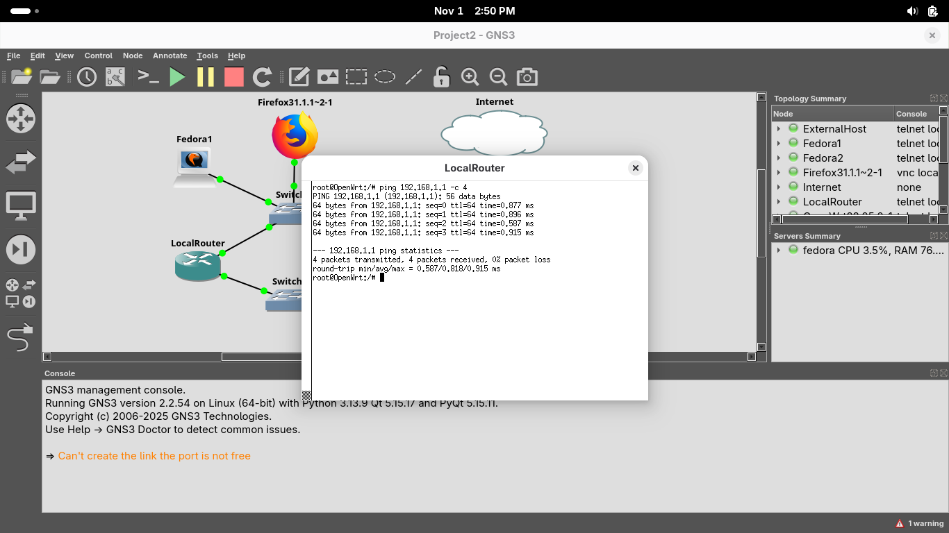
Run the following command from the OpenWRT Console to ping the Firewall Appliances LAN Interface:
root@openwrt:~$ ping 192.168.1.1 -c 4
Resulting Output:
Exit the OpenWRT console and right-click on our Fedora2 workstation and select stop from the menu options
We must restart the device to retrieve a new IP Address, right-click and hit start then select the console
Run the following commands from the second fedora workstations console to ping the router and firewall:
[fedora@fedora-cloud ~]$ ping 10.10.10.1 -c 4
[fedora@fedora-cloud ~]$ ping 192.168.1.1 -c 4
You should find that the router replies but the firewall does not. This doesn't mean your requests failed
The workstation is aware of the router which is aware of the firewall. The reply has no known target IP
The firewall knows about the two networks it's connected to which are 192.168.1.1/24 and 66.67.68.1/24
The firewall has no longer of our 10.10.10.1/24 subnetwork, we need to tell the appliance where to route
Head back to our Firefox TigerVNC console and from the menu at the top head to System then to Routing:
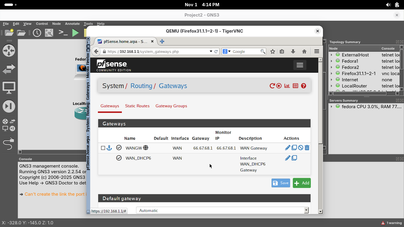
On the System / Routing / Gateways page, click Add to add a new gateway using the options shown below:
• Disabled: Off
• Interface: LAN
• Address Family: IPv4
• Name: LocalRouter
• Gateway: 192.168.1.254
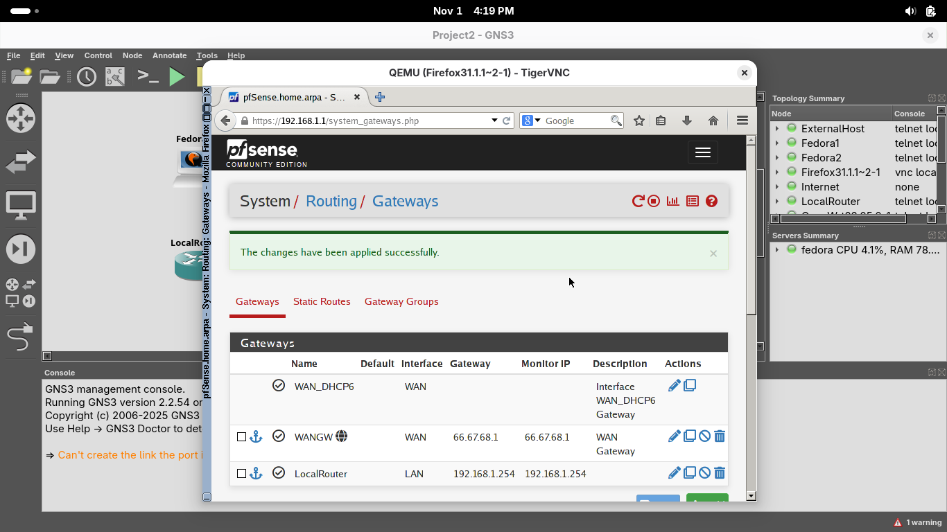
Click save, then the new gateway should appear on the System / Routing / Gateways page, hit apply changes:
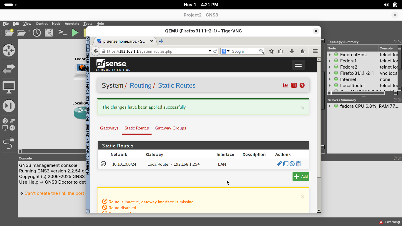
On the System / Routing / Gateways page, select the Static Routes option and click on Add to add a route:
• Destination Network: 10.10.10.1 / 24
• Gateway: LocalRouter - 192.168.1.254
Click save, then the new route should appear on the System / Routing / Static Routes page, hit apply changes:
From the menu at the top, select the Firewall option and select the Rules option, then select the LAN tab
By default, the firewall allows all traffic from the LAN net 192.168.1.1/24. Let's make it include our subnet
From the Firewall / Rules / LAN page, click on the Edit button (the Pencil) for the second firewall rule
From the Firewall / Rules / Edit page, scroll down an change the Source from LAN Subnets to Any and click save
On the Firewall / Rules / LAN page, click Apply Changes. We should be able to reach the firewall and beyond
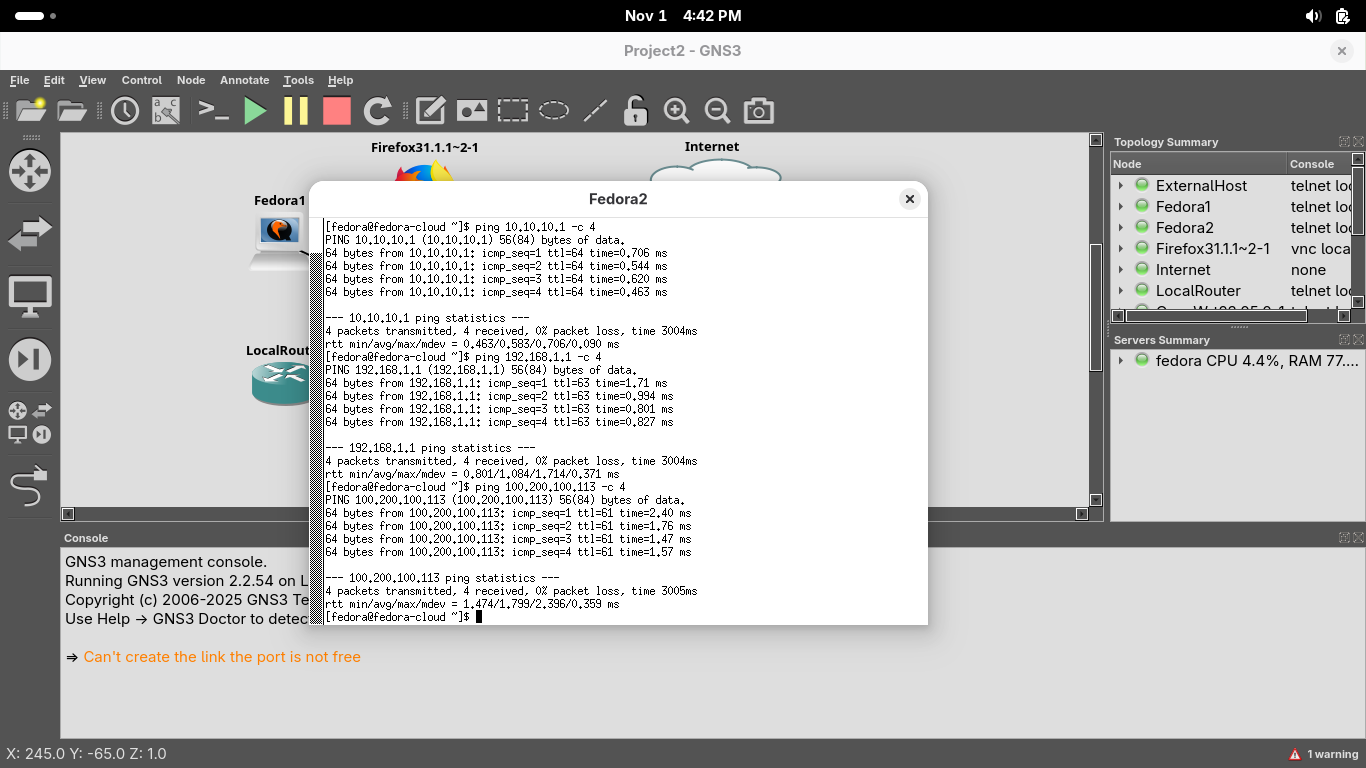
Run the following commands from our Fedora2 Console to ping the InternalRouter, Firewall, and ExternalHost:
[fedora@fedora-cloud ~]$ ping 10.10.10.1 -c 4
[fedora@fedora-cloud ~]$ ping 192.168.1.1 -c 4
[fedora@fedora-cloud ~]$ ping 100.200.100.113 -c 4
Resulting Output:
Congratulations, in this lab you explored and configured a small Local Area Network environment hosted in GNS3
You learned some basic firewall management skills for pfSense and learned how to configure some OpenWRT Routers