This lab introduces you to the fundamentals of Virtual Private Networks by guiding you through the design and deployment of an IPSec tunnel using pfSense firewalls inside a GNS3‑based virtual network environment. The exercise focuses on building a secure site‑to‑site connection, giving you hands‑on experience with real firewall interfaces, routing behavior, and encrypted traffic flow.
Cybrary is a well established and free IT training platform with several intuitive labs to explore
A paid subscription with more advanced labs is available as well outside the scope of this platform
Head to https://www.cybrary.it to create a free account for learning available on their platform
Head to VPN Basics to complete this lab for yourself or you can perform it on your homelab below
Quick Links:
Requirements:
• Windows PC w/ Internet Connection
• 2 USB Flash Drives w/ at least 64GB Capacity
• Unused PC w/ at least 4GB of Memory
1. VPN Overview
A Virtual Private Network (VPN) is a technology that establishes a secure connection over a public network
VPNs provide an encrypted channel for users to access internal resources and to safely transmit their data
VPNs ensure privacy, confidentiality, and security by leveraging encryption protocols to scramble the data
VPNs support multiple authentication methods, including passwords and cryptographic digital certificates
VPNs can also help hide a user's true location and IP address, thereby providing a degree of anonymity
• Point-to-Point Tunneling Protocol (PPTP):
PPTP is an older protocol used on Windows, it uses an insecure authentication method and an outdate cipher
Unfortunately you will still find PPTP in use as it is easy to set up and comes bundled free with Windows
• Layer 2 Tunneling Protocol (L2TP):
L2TP is similar to PPTP. Whereas PPTP uses TCP for connection stability, L2TP uses UDP to improve speed
L2TP is often combined with another VPN protocol IPsec, as L2TP tunnels do not encrypt data on their own
• Secure Socket Tunneling Protocol (SSTP):
SSTP uses SSL 3.0 to create private connections, it is often used to bypass firewall since it uses TCP 443
Since SSL 3.0 is vulnerable to the POODLE attack, there is now some risk involved in using this protocol
• Internet Security Protocol (IPsec):
IPsec is a collection of tools that add authentication, encryption, and data integrity to the IP protocol
The primary addition it makes is the secure exchange of keys. IPsec will be discussed in more detail below
• OpenVPN:
OpenVPN is an open-source VPN solutions that uses the OpenSSL library to implement secure data encryption
OpenVPN supports certificate-based authentication and pre-shared keys for verifying the endpoints identity
As mentioned above, IPsec is an added extension to the IP protocol which moves packets between networks
A typical IP pack is shown below. The TCP header encapsulates the data, which is encapsulated by the IP
|
IP Header |
TCP Header |
Data |
IPsec uses the Authentication Header (AH) protocol, the Encapsulation Security Protocol (ESP) or even both
These provide authentication and encryption. Below, we see one IP packet using AH and one packet using ESP
|
IP Header |
AH Header |
TCP Header |
Data |
|
ESP Header |
IP Header |
TCP Header |
Data |
ESP Trailer |
Note the packets show above will look slightly different depending on the model of IPsec that's being used
IPsec supports both tunnel mode and transport mode. The models shown above are representing transport mode
Transport mode is used to secure peer-to-peer connections, while tunnel mode will connect two locations
Tunnel mode also adds a second IP header to the IP packets, here is a view of what that packet looks like:
|
Tunnel IP Header |
IP Header |
AH Header |
TCP Header |
Data |
|
Tunnel IP Header |
ESP Header |
IP Header |
TCP Header |
Data |
ESP Trailer |
The key takeaway here is that IP alone is not secure, but protocols can be added to it to make it secure
1. Tunnel Creation Trigger
2. Internet Key Exchange (IKE) Phase 1
3. Internet Key Exchange (IKE) Phase 2
4. Data Transfer
5. Tunnel Termination
The first step is when a router, firewall, VPN appliance, or VPN client software sees interesting traffic
When a firewall sees traffic designed for the other network in a site-to-site, it views it as interesting
When deemed as interesting, it will initiate a secure IPsec connection to the appliance at the other end
However in the case of site-to-site connections, the admin will quite often initiate the tunnel manually
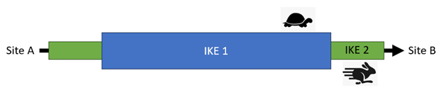
Next comes the IKE Phase 1 and the IKE Phase 2 stages. Think of these as a tunnel inside of another tunnel
IKE Phase 1 is mostly concerned with authentication, while IKE Phase 2 encrypts and passes along the data
Data is sent from one side of the VPN tunnel to the other, these tunnels are called Security Associations
IKE Phase 1 is computationally heavier and slower than IKE Phase 2, this is why two tunnels are preferred
One for slow, one-time asynchronous operations and an encapsulated tunnel for fast synchronous operations
Packets are sent between the initiator and the receiver as long as the Security Association stays valid
When the Security Association times out, the tunnel is torn down, sometimes caused by connectivity issues
Administrators should monitor the state of their VPN tunnels for Security Associations that need restarted
The description above is a bit simplified. IPsec is a complex protocol suite, but this gives you the basics
In the next lesson, you will configure a site-to-site VPN between two networks by using IPsec and pfSense
2. Install Arch Linux
Arch Linux is a lightweight, flexible, and minimalist Linux distribution designed to offer full control
Its philosophy centers on simplicity, not in the sense of being beginner-friendly, but in the sense of
keeping the system free of unnecessary layers so users can build exactly the system they want from scratch
According to the official website, Arch Linux is a "simple, lightweight and flexible Linux distribution"
In this lab we will utilize the Arch Linux Distribution to emulate a site-to-site VPN for connecting hosts
Arch Linux is unique in that you must install the operating system piece by piece through the command line
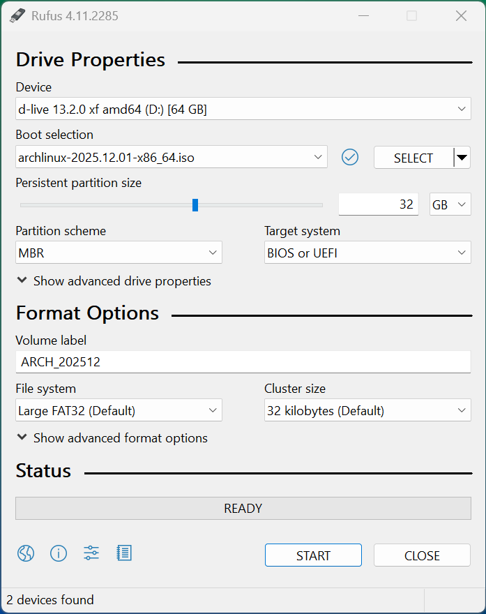
Download Arch Linux Image: Arch Linux Download Mirrors
Download Rufus Disk Imaging Software: Rufus Official Download
Insert USB Flash Drive, run rufus.exe, select target drive, select the Arch Linux Image, then hit start:
Remove the USB Flash Drive and Insert into unused PC. Start PC and press the hot boot key at the startup:
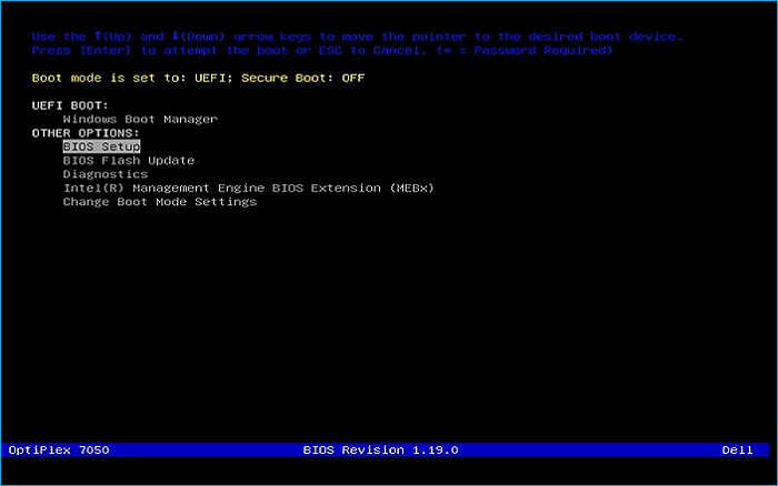
Select the option to boot from your USB Flash Drive, then select the Arch Linux install medium from below:
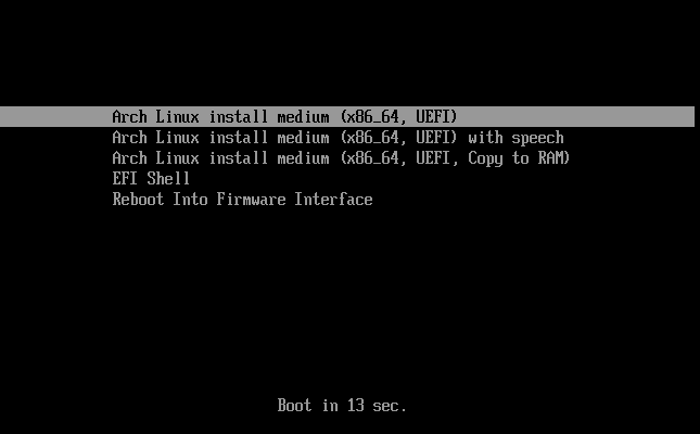
Once the operating system loads you will be presented with a root command prompt to install the OS from:
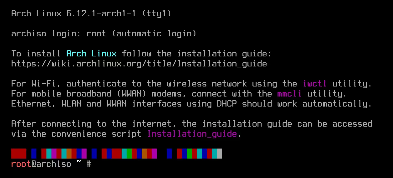
Previously it was required to build this operating system line by line with a command for each portion
Now there are several installer scripts which come bundled with arch which make the install much easier
For the sake of having a deep understanding of the OS, in this lab we will be installing the classic way
We will be customizing each aspect of the OS, start by running the command to list the keyboard layouts:
root@archiso ~ # localectl list-keymaps
The list is large so don't get decision paralysis, run the following command to set to the default us:
root@archiso ~ # loadkeys us
Run the following command from the Arch Installation Terminal to set the operating systems font package:
root@archiso ~ # setfont aply16
Now run the following command from the Arch Installation Terminal to verify the systems boot mode:
root@archiso ~ # cat /sys/firmware/efi/fw_platform_size
If the system returns 64 or 32 you are in UEFI 64-bit or 32-bit mode, if no results you're in BIOS mode
Plug in your ethernet cable and run the following commands to check for an active internet connection:
root@archiso ~ # ip link
root@archiso ~ # ip addr show
root@archiso ~ # ping ping.archlinux.org
Next run the following command from the Arch Installation Terminal to update the systems clock and time:
root@archiso ~ # timedatectl
Next run the following command from the Arch Installation Terminal to list the available disks to install:
root@archiso ~ # lsblk
The drives will be listed and you should tell your target based on the size, remove the +- from the name
Run the following command from the Arch Installation Terminal to begin partitioning with the fdisk tool:
root@archiso ~ # fdisk /dev/nvme0n1
The fdisk tool can be used to create a disk partitioning format that our operating system will follow:
• Press n to create a new partition
• Enter 1 as the partition number
• Press Enter to accept the default first sector
• Set the last sector to +1G for a 1GB partition
• Enter y to remove the vfat signature
• Change to EFI System type by pressing t and selecting partition 1 and option 1
• Press n to create another partition
• Enter 2 as the partition number
• Press Enter to accept the default first sector
• Set the last sector to +4G for a 4GB partition
• Change to Linux Swap type by pressing t and selecting partition 2 and option 19
• Press n to create another partition
• Enter 3 as the partition number
• Press Enter to accept the default first sector
• Press Enter to accept the default last sector
• Change to Linux x86-64 Root type by pressing t and selecting partition 3 and option 23
• Press p and confirm you see all three partitions
• Press w to write changes to disk and exit fdisk
Run the following commands from the Arch Installer Terminal to format and initialize our new partitions:
root@archiso ~ # mkfs.ext4 /dev/nvme0n1p3
root@archiso ~ # mkswap /dev/nvme0n1p2
root@archiso ~ # mkfs.fat -F 32 /dev/nvme0n1p1
Run the following command from the Arch Installer Terminal to mount the partitions and enable the swap:
root@archiso ~ # mount /dev/nvme0n1p3 /mnt
root@archiso ~ # mount --mkdir /dev/nvme0n1p1 /mnt/boot
root@archiso ~ # swapon /dev/nvme0n1p2
Run the following command to install basic linux utilities to be carried over to our installed system:
root@archiso ~ # pacstrap -K /mnt intel-ucode iproute2 nano sudo base bash linux linux-firmware
Run the following command from the Arch Installation Terminal to generate the fstab file and UUID labels:
root@archiso ~ # genfstab -U /mnt >> /mnt/etc/fstab
Run the following command from the Arch Installation Terminal to change the root into the new systems root:
root@archiso ~ # arch-chroot /mnt
You will notice that the terminals prompt has changed to [root@archiso /]#, indicating we are on system
Run the following commands from the Arch Installation Terminal to set the timezone, in this case EST time:
[root@archiso /]# ln -sf /usr/share/zoneinfo/EST
[root@archiso /]# hwclock --systohc
Run the following commands from the Arch Installation Terminal to set the localization and keyboard layout:
[root@archiso /]# locale-gen
[root@archiso /]# echo 'en_US.UTF-8 UTF-8' >> /etc/locale.gen
[root@archiso /]# echo 'LANG=en_US.UTF-8' >> /etc/locale.conf
[root@archiso /]# echo 'KEYMAP=us' >> /etc/vconsole.conf
Run the following command from the Arch Installation Terminal to set our machines network hostname:
[root@archiso /]# echo 'itlab-center-arch' >> /etc/hostname
Run the following commands from the Arch Installation Terminal to set a root password for the arch system:
[root@archiso /]# passwd
Run the following commands from the Arch Installation Terminal to install the Grub bootloader and scripts:
[root@archiso /]# sudo pacman -S grub efibootmgr
[root@archiso /]# grub-install --target=x86_64-efi --efi-directory=/boot --bootloader-id=GRUB
[root@archiso /]# grub-mkconfig -o /boot/grub/grub.cfg
Run the following commands from the Arch Installation Terminal to reboot into our newly created system:
[root@archiso /]# exit
root@archiso ~ # umount -R /mnt
root@archiso ~ # reboot
After the reboot our system will load into the GRUB bootloader and present us with a command line after:
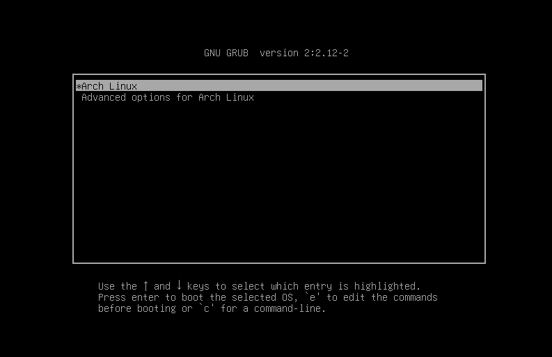
Hit enter to select the first option and you will be presented with the command line for your new system
Before moving on to the next section for our lab we need to login, username root and the password you set
3. Install Lab Tools
Though we now have our base operating system, we will be using several more tools in this lesson on VPNs
Let's go and install these tools including a desktop environment, GNS3, Docker, and the VM dependencies
Run the following command from the Arch Linux Terminal to create our initial network configuration file:
[root@itlab-center-arch ~]# nano /etc/systemd/network/20-wired.network
From the nano text editor, type out the few lines listed below, then CTRL+O to save and CTRL+X to exit:
[Match]
Name=en*
[Network]
DHCP=yes
Run the following commands from the Arch Linux Terminal to enable and start the network and DNS services:
[root@itlab-center-arch ~]# systemctl enable systemd-networkd
[root@itlab-center-arch ~]# systemctl start systemd-networkd
[root@itlab-center-arch ~]# systemctl enable systemd-resolved
[root@itlab-center-arch ~]# systemctl start systemd-resolved
Run the following commands from the Arch Linux Terminal to synchronize our packages and reboot the system:
[root@itlab-center-arch ~]# pacman -Syu
[root@itlab-center-arch ~]# reboot
Run the following commands from the Arch Linux Terminal to install XORG and the GNOME desktop environment:
[root@itlab-center-arch ~]# pacman -S xorg xorg-server --no-confirm
[root@itlab-center-arch ~]# pacman -S gnome --no-confirm
[root@itlab-center-arch ~]# systemctl enable gdm.service
[root@itlab-center-arch ~]# reboot
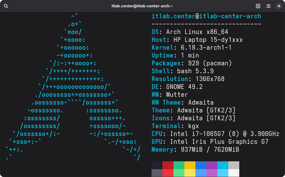
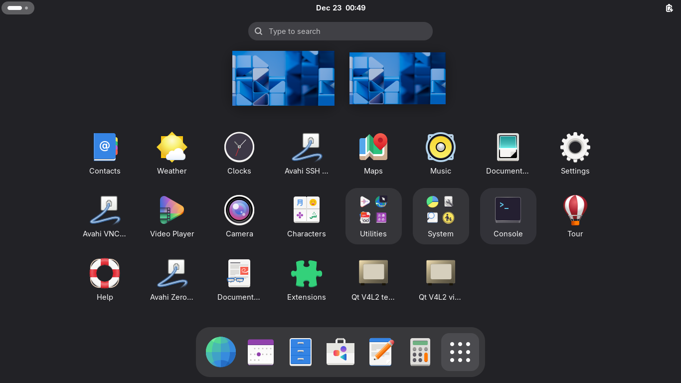
Now that we have the graphic environment installed, our OS will boot to a login screen, then the desktop:
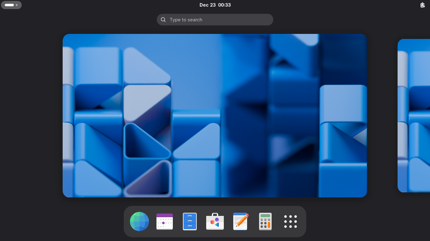
Now we are in business. Many programs however don't supporting running as root so we create another user
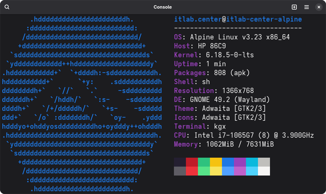
To reach the Terminal from within GNOME, click the 9 dots at the bottom and click the Console application:
Run the following commands from the Arch Linux Terminal to create a local user account and add sudo to it:
[root@itlab-center-arch ~]# useradd -m -G wheel -s /bin/bash itlab.center
[root@itlab-center-arch ~]# passwd itlab.center
[root@itlab-center-arch ~]# nano /etc/sudoers
Now find the line below and remove the hashtag and space to allow members of the wheel group to use sudo:
# %wheel ALL=(ALL:ALL) ALL
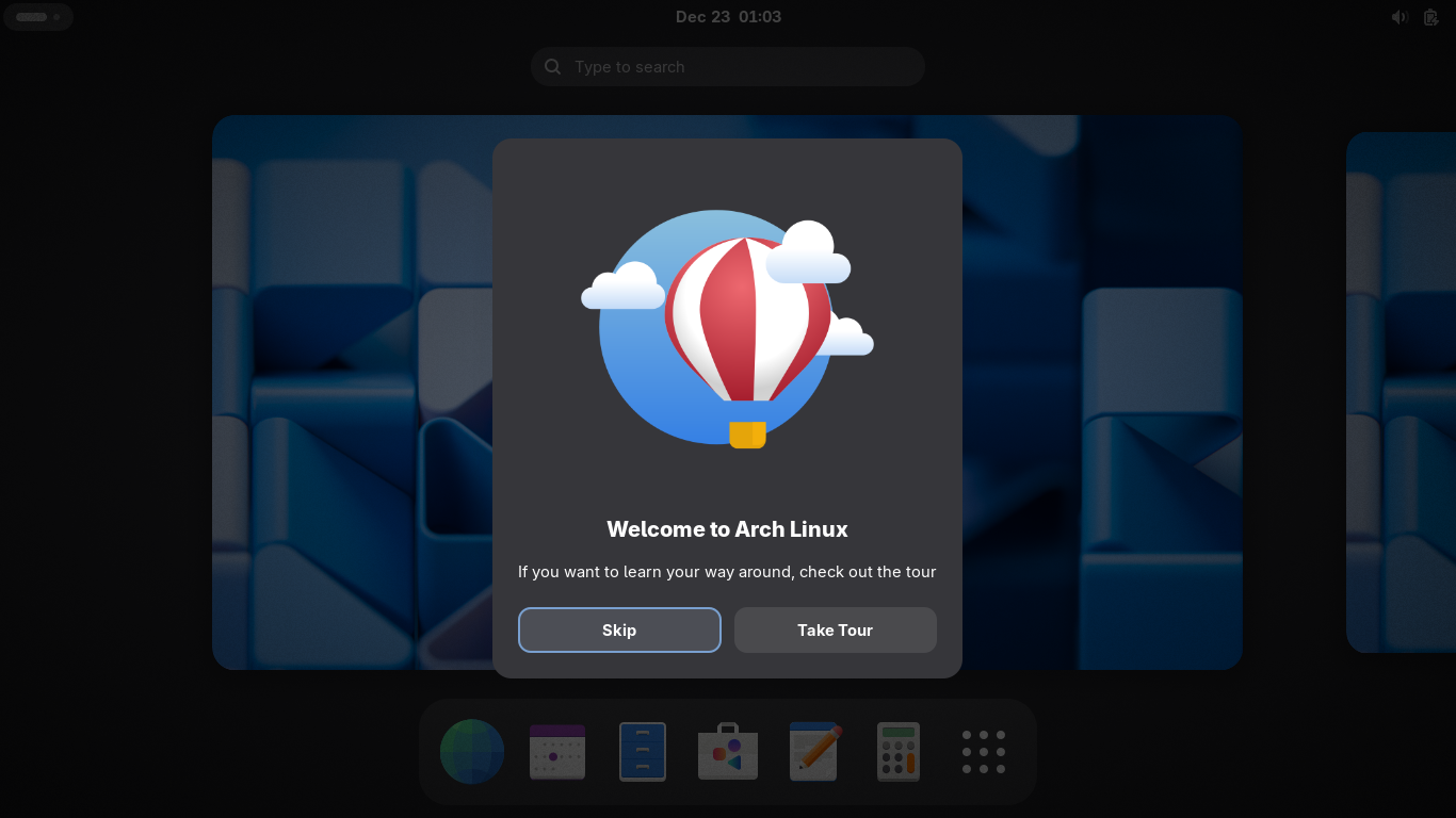
Log out or reboot the operating system and log back in with our new account, we see that the tour works:
GNS3 is an application which allows you to deploy virtual network topologies with official device images
In this lab we will be using the GNS3 application as our network emulator to build the VPN servers from
Run the following commands from the Arch Linux Terminal to install all the GNS3 dependency programs:
[itlab.center@itlab-center-arch ~]$ sudo pacman -S --needed vim git base-devel --no-confirm
[itlab.center@itlab-center-arch ~]$ git clone https://aur.archlinux.org/yay-bin.git
[itlab.center@itlab-center-arch ~]$ cd yay-bin
[itlab.center@itlab-center-arch yay-bin]$ makepkg -si
Run the following commands from the Arch Linux Terminal to install GNS3 and the full GNS3 utility suite:
[itlab.center@itlab-center-arch yay-bin]$ cd ..
[itlab.center@itlab-center-arch ~]$ yay -S qemu docker vpcs dynamips libvirt ubridge inetutils
[itlab.center@itlab-center-arch ~]$ yay -S gns3-server gns3-gui
We will be using Docker later in this lab to build container appliances for our virtual network topology
Run the following commands from the Arch Linux Terminal to enable and start docker and modify permissions:
[itlab.center@itlab-center-arch ~]$ sudo systemctl enable docker
[itlab.center@itlab-center-arch ~]$ sudo systemctl start docker
[itlab.center@itlab-center-arch ~]$ sudo usermod -aG docker $USER && reboot
Unfortunately GNS3 still calls Version 1.24 of the Docker API which is older than the minimum required
Run the following command from the Arch Linux Terminal to edit the docker applications service config:
[itlab.center@itlab-center-arch ~]$ sudo systemctl edit docker
Navigate to the first empty line in the configuration file and type the following, CTRL+O & CTRL+X to save
[Service]
Environment="DOCKER_MIN_API_VERSION=1.24"
Run the following commands from the Arch Linux Terminal to apply these changes to the docker service:
[itlab.center@itlab-center-arch ~]$ sudo systemctl daemon-reload
[itlab.center@itlab-center-arch ~]$ sudo systemctl restart docker
Run the following command from the Arch Linux Terminal to install additional Docker application plugins:
[itlab.center@itlab-center-arch ~]$ sudo pacman -S docker-buildx docker-compose --no-confirm
Run the following command from the Arch Linux Terminal to install TigerVNC for our virtual vnc consoles:
[itlab.center@itlab-center-arch ~]$ sudo pacman -S tigervnc --no-confirm
Unfortunately there is a bug in the working version of python-pyqt5 5.15.11-3 which breaks the GNS3 tool
Run the following command from the Arch Linux Terminal to downgrade this package and fix your GNS3 install:
[itlab.center@itlab-center-arch ~]$ sudo pacman -U https://archive.archlinux.org/packages/p/python-pyqt5/python-pyqt5-5.15.11-2-x86_64.pkg.tar.zst
[itlab.center@itlab-center-arch ~]$ echo 'IgnorePkg = python-pyqt5' >> /etc/pacman.conf
Our application should be ready to go now. In the future this step may not be necessary but here we are
Run the following command from the Arch Linux Terminal to launch the GNS3 application in the background:
[itlab.center@itlab-center-arch ~]$ gns3 &
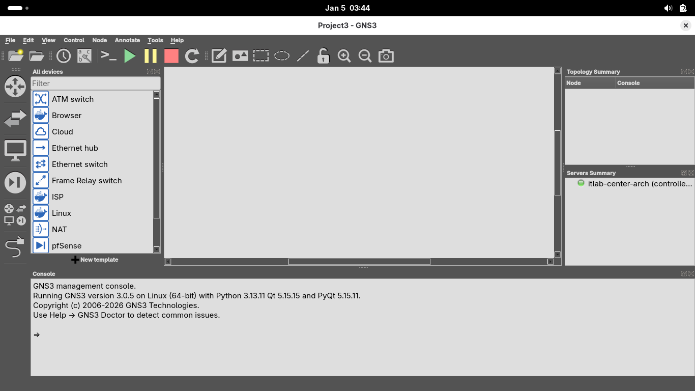
Resulting Output:
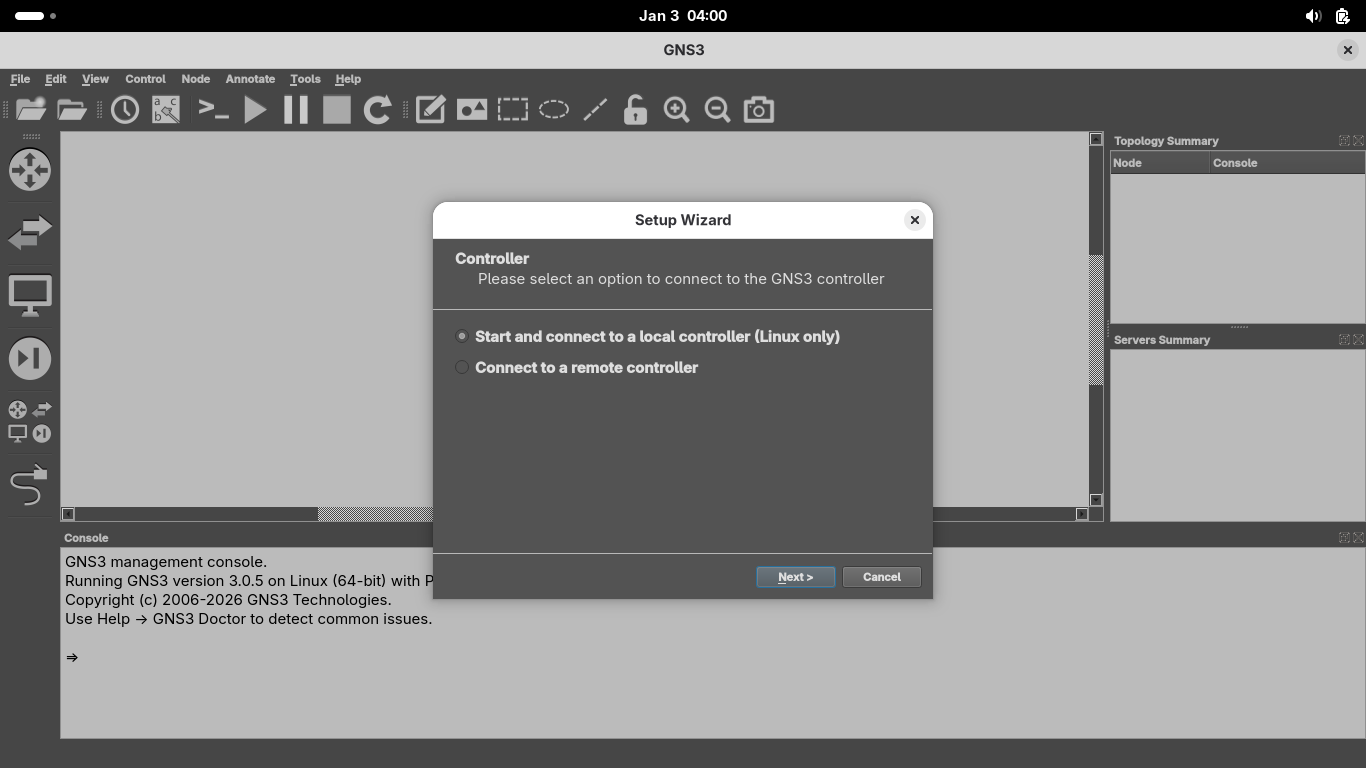
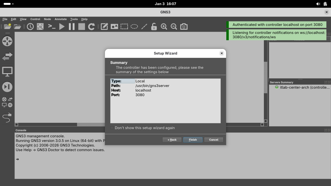
Once GNS3 opens you will be directed to the setup wizard. Select 'Start and connect to a local controller'
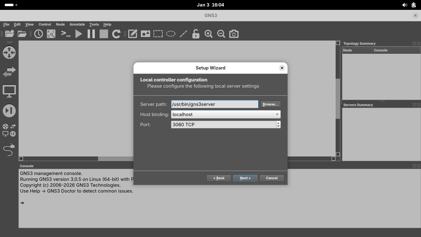
On the Local Controller Configuration page, ensure /usr/bin/gns3server is the path and the port is 3080:
Once the application connects to the local server, you will be greeted with a success page, click finish:
We now have our platform running on which we will construct our network topology for this VPN lab exercise
4. Install pfSense Appliance
Before we can build the VPN connections we must create the environment they will be making tunnels within
Our IPsec tunnel will be managed by two pfSense firewall appliances, let's walk through installing them
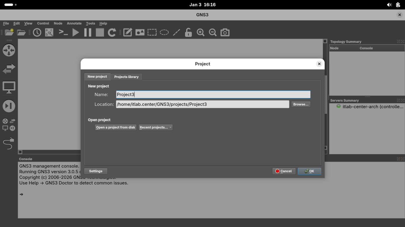
From the GNS3 GUI window click on File > New Blank Project > title your project as Project3 and hit ok:
We must import appliances in order to simulate them on our virtual network, head to File > New Template:
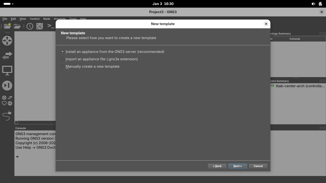
Install an appliance from the GNS3 server > Firewalls > pfSense > Install the appliance on the main server
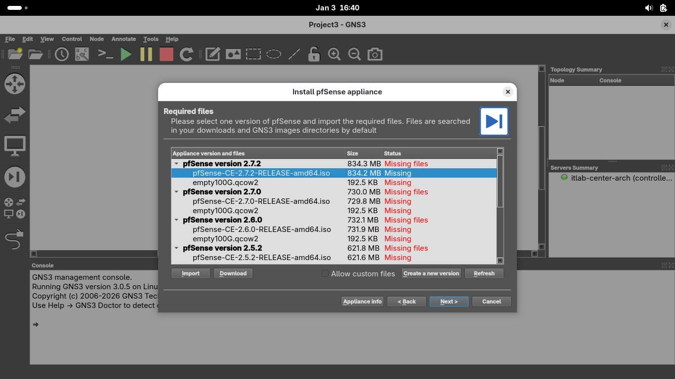
Click on the image file displayed as missing, you can find the repository at pfSense Image Repository
Head to that link in your web browser and download the pfSense-CE-2.7.2-RELEASE-amd64.iso.gz image file
Run the following command from the Arch Linux Terminal to unzip our newly downloaded pfSense image file:
[itlab.center@itlab-center-arch ~]$ gunzip ~/Downloads/pfSense-CE-2.7.2-RELEASE-amd64.iso.gz
Now click on the empty100G.qcow2 file in GNS3 and download it by clicking on the download button below it
From the GNS3 Install psSense appliance menu, click 'Allow custom files' and refresh to populate files:
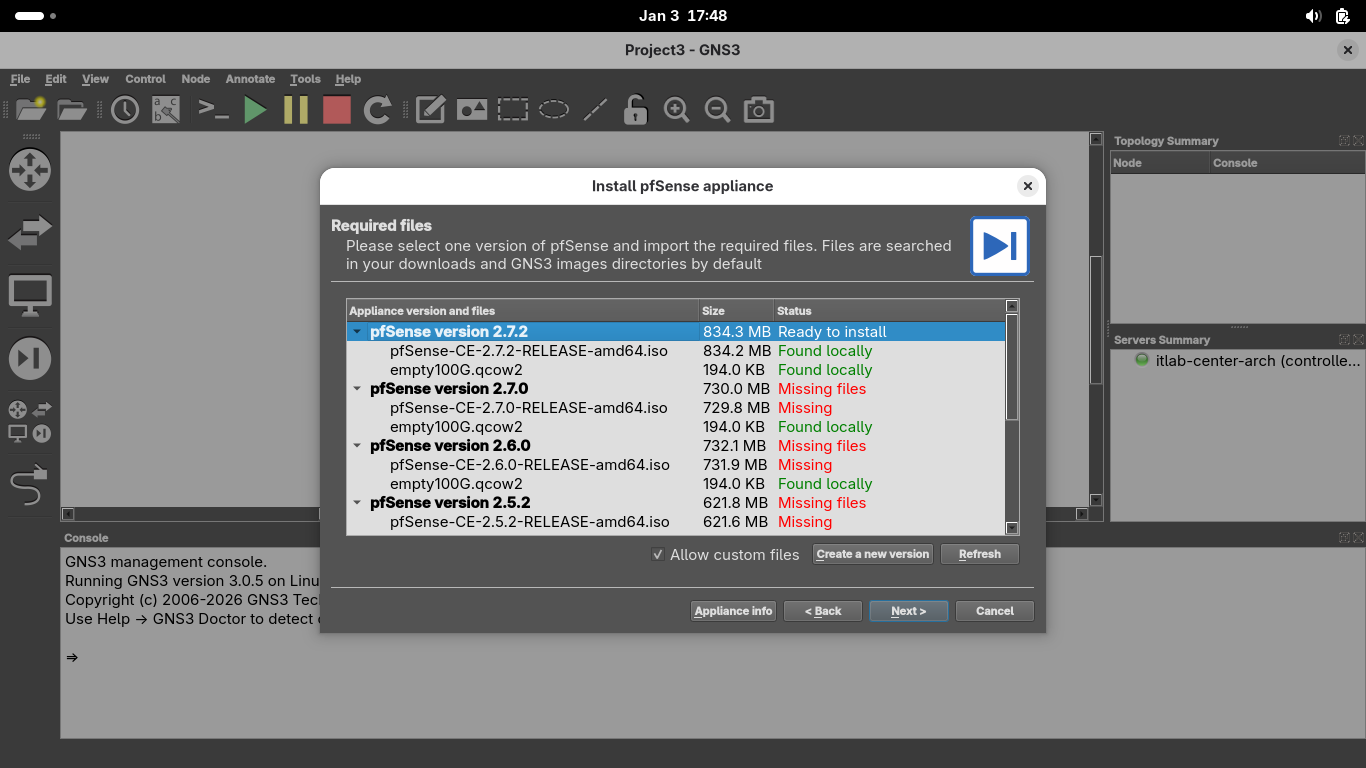
Select the psSense 2.7.2 version and click Next > OK > Finish to install the new GNS3 Appliance Template:
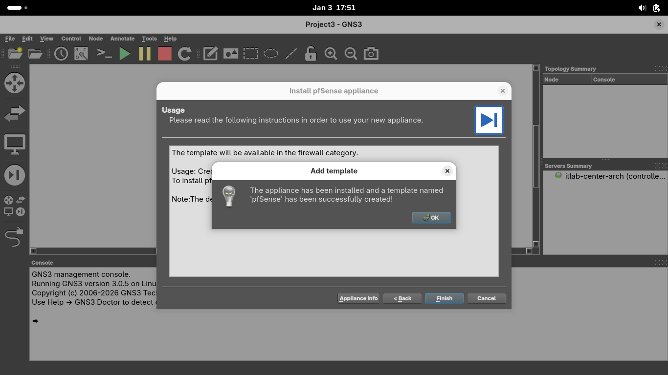
We can now use this appliance to later initiate the VPN connections that are built into pfSense, click OK
5. Build Docker Containers w/ Alpine
Docker is a container deployment tool which we will use in this lab to create virtual containers as hosts
Alpine Linux is a lightweight distribution of Linux which is small and resource efficient as a container
Rather than importing our ISP Router and the Hosts as appliances, we will create each of them from scratch
This moves us away from the black box of vendor provided appliances to understand the fundamental kernel
This will give you a deep understanding of routing protocols and underlying software enabling connectivity
We have 3 separate appliances to make, one ISP router appliance, a workstation and a web browser appliance
Run the following command from the Arch Linux Terminal to create the Dockerfile for our ISP router device:
[itlab.center@itlab-center-arch ~]$ nano Dockerfile-ISP
Being the edge ISP Router, this appliance will be responsible for forwarding traffic between the networks
The routing protocols which enable this are the Border Gateway Protocol and the Open Shortest Path First
Our ISP router will run Alpine Linux as the OS and must include several networking tools, type out below:
# 1. Load Base Operating System
FROM alpine:latest
# 2. Update and Install Packages
RUN apk update && apk add --no-cache frr iproute2 iptables tcpdump bash mtr xvfb xterm font-noto terminus-font dnsmasq
# 3. Set Display Environment
ENV DISPLAY=:0
# 4. Configure Routing Protocols
RUN sed -i 's/zebra=no/zebra=yes/g' /etc/frr/daemons && \
sed -i 's/bgpd=no/bgpd=yes/g' /etc/frr/daemons
# 5. Configure Router Persistence
RUN touch /etc/frr/frr.conf && \
chown frr:frr /etc/frr/frr.conf && \
chmod 664 /etc/frr/frr.conf
touch /etc/dnsmasq.conf
# 6. Boot Sequence
RUN echo "#!/bin/sh" > /start.sh && \
echo "rm -f /tmp/.X0-lock" >> /start.sh && \
echo "sysctl -w net.ipv4.ip_forward=1" >> /start.sh && \
echo "/usr/lib/frr/frrinit.sh start" >> /start.sh && \
dnsmasq --conf-file=/etc/dnsmasq.conf &" >> /start.sh && \
echo "Xvfb :0 -screen 0 1024x768x24 -ac &" >> /start.sh && \
echo "sleep 2" >> /start.sh && \
echo "exec xterm -geometry 73x23+0+0 -bg '#000000' -fg '#00eeee' -fa 'Monospace' -fs 16 -cr '#00eeee' -bc -hold -e /bin/bash" >> /start.sh && \
chmod +x /start.sh
ENTRYPOINT ["/start.sh"]
Next we will create a Dockerfile for some standard linux hosts, we strip out the heavy routing protocols
We will however add in some useful tools to allow us to test connectivity and perform basic host commands
Run the following command from the Arch Linux Terminal to create the Dockerfile for our Linux Host devices:
[itlab.center@itlab-center-arch ~]$ nano Dockerfile-Host
Our Host devices will also run Alpine Linux as the OS and include networking testing tools, type out below:
# 1. Load Base Operating System
FROM alpine:latest
# 2. Update and Install Packages
RUN apk update && apk add --no-cache bash iproute2 tcpdump mtr curl bridge-utils xvfb xterm font-noto terminus-font
# 3. Set Display Environment
ENV DISPLAY=:0
# 4. Boot Sequence
RUN echo "#!/bin/sh" > /start.sh && \
echo "rm -f /tmp/.X0-lock" >> /start.sh && \
echo "udhcpc -i eth0" >> /start.sh && \
echo "Xvfb :0 -screen 0 1024x768x24 -ac &" >> /start.sh && \
echo "sleep 2" >> /start.sh && \
echo "exec xterm -geometry 73x23+0+0 -bg '#000000' -fg '#00eeee' -fa 'Monospace' -fs 16 -cr '#00eeee' -bc -hold -e /bin/bash" >> /start.sh && \
chmod +x /start.sh
ENTRYPOINT ["/start.sh"]
Lastly we will create a Dockerfile for an out of band web browser to manage the pfSense firewall appliance
Run the following command from the Arch Linux Terminal to create the Dockerfile for our OOB Web Browsers:
[itlab.center@itlab-center-arch ~]$ nano Dockerfile-Browser
Our Browser devices will also run Alpine Linux and must include web-fonts for the display, type out below:
# 1. Load Base Operating System
FROM alpine:latest
# 2. Update and Install Packages
RUN apk update && apk add --no-cache firefox fluxbox dbus dbus-x11 ttf-dejavu font-noto xvfb bash iproute2
# 3. Setup The Environment
ENV DISPLAY=:0
ENV HOME=/root
# 4. Boot Sequence
RUN echo "#!/bin/sh" > /start.sh && \
echo "rm -f /tmp/.X0-lock" >> /start.sh && \
echo "udhcpc -i eth0" >> /start.sh && \
echo "dbus-uuidgen > /var/lib/dbus/machine-id" >> /start.sh && \
echo "Xvfb :0 -screen 0 1024x768x24 -ac &" >> /start.sh && \
echo "sleep 2" >> /start.sh && \
echo "fluxbox &" >> /start.sh && \
echo "sleep 1" >> /start.sh && \
echo "exec dbus-run-session -- firefox --window-size 1024,768" >> /start.sh && \
chmod +x /start.sh
ENTRYPOINT ["/start.sh"]
Run the following commands from the Arch Linux Terminal to build the Docker images from our Dockerfiles:
[itlab.center@itlab-center-arch ~]$ sudo docker build -t isp -f Dockerfile-ISP .
[itlab.center@itlab-center-arch ~]$ sudo docker build -t host -f Dockerfile-Host .
[itlab.center@itlab-center-arch ~]$ sudo docker build -t browser -f Dockerfile-Browser .
From the GNS3 GUI window, click File > New Template > Manually Create a New Template > Docker Containers:
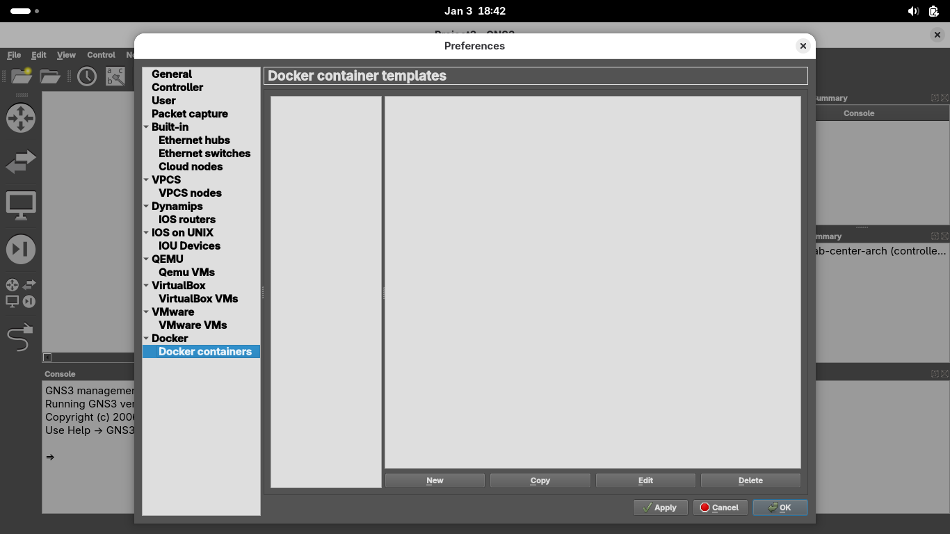
From the Preferences Windows, under docker containers, click New > Existing Image > ips:latest > Next:
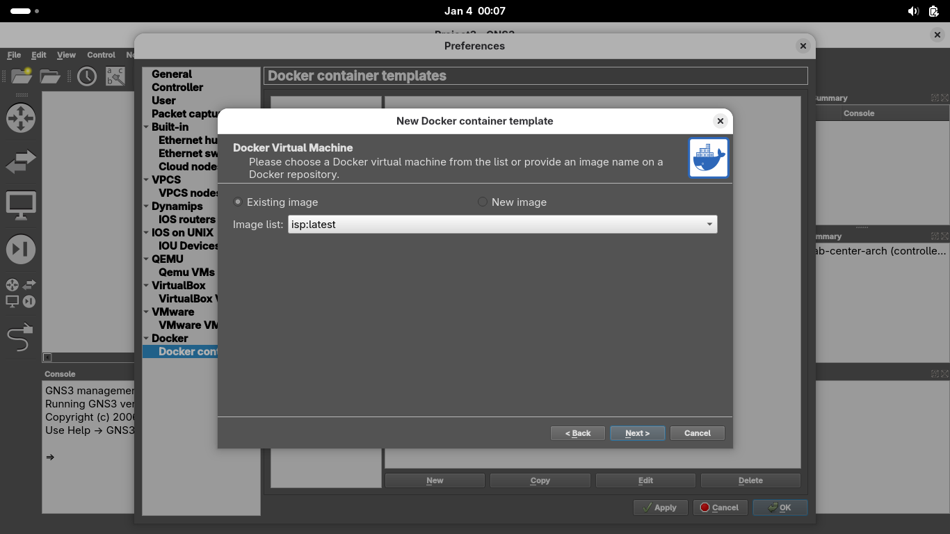
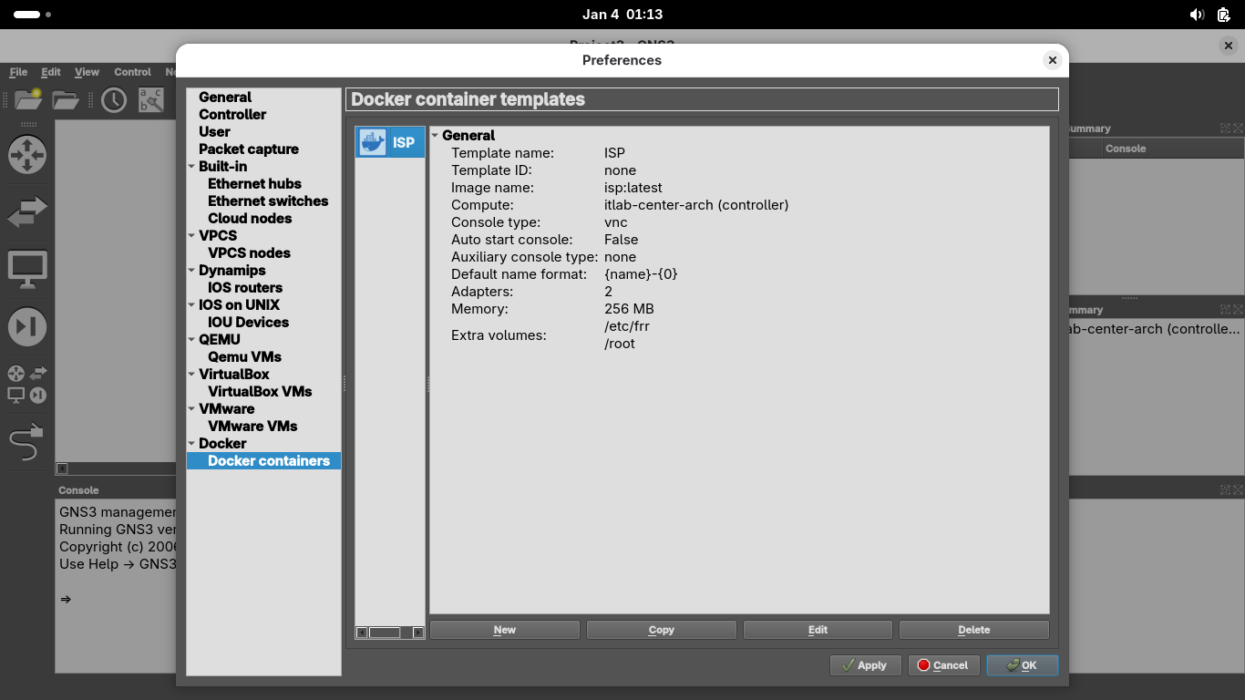
Name the container 'ISP', grant it 2 network adapters, set console as vnc, then select Finish > ISP > Edit
Set the containers memory to 256 MB, then head over to advanced and add both /etc and /root to persistence:
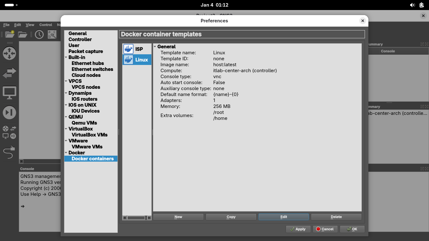
From the Preferences Windows, under docker containers, click New > Existing Image > host:latest > Next
Name the container 'Linux', grant it 1 network adapter, set console as vnc, then select Linux > Edit:
Set the containers memory to 256 MB, then head over to advanced and add /root and /home to persistence:
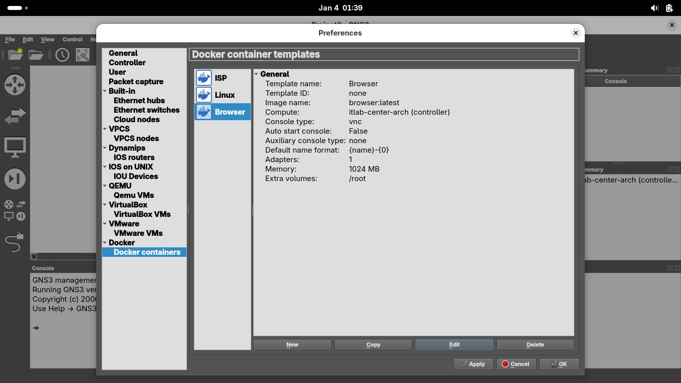
From the Preferences Windows, under docker containers, click New > Existing Image > browser:latest > Next
Name the container 'Browser', grant it 1 network adapter, set console as vnc, then select Browser > Edit:
Set the containers memory to 1024 MB (1GB), then head over to advanced and add /root to the persistence:
Now click on Apply and then OK. Our Docker containers will be available to deploy as appliances in GNS3
6. Deploy Virtual Network Topology
With our appliances available, we are ready to construct the environment which will run our lab exercise
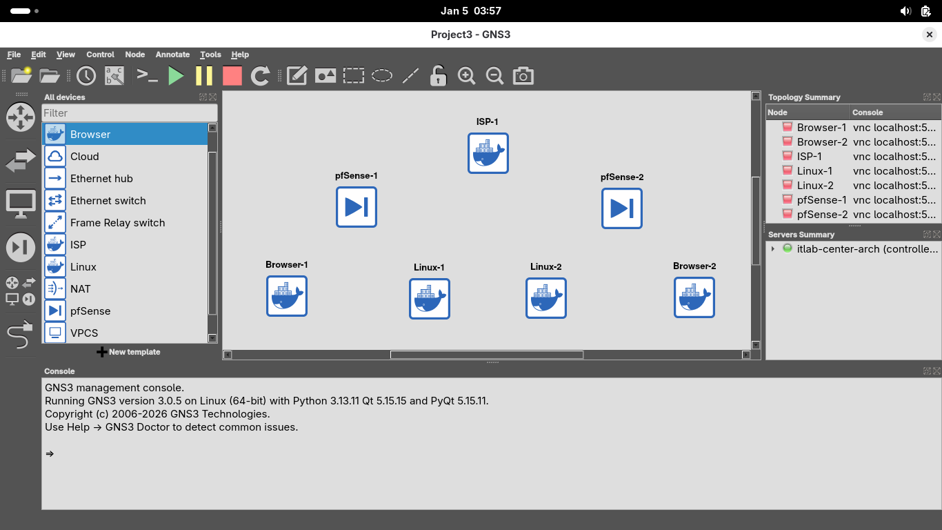
From the GNS3 applications topology view, click on the 'Browse all devices' bottom at the bottom left menu
Drag and drop one ISP Router, two pfSense Firewalls, two Linux Hosts and two Browsers into this layout:
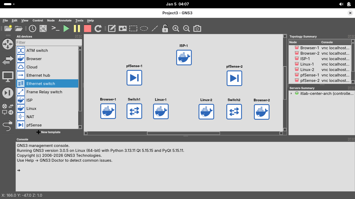
Now drag and drop a switch for each of the two internal networks to sit flush between the host and browser
Now click on the ethernet cable icon to add links within our internal networks, use em1 on the pfSense:
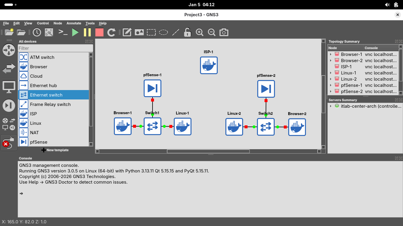
Now connect each of the pfSense firewalls to the ISP router, make sure to use interface em0 on the pfSense
You can use either of the interfaces on the ISP router, for simplicity use eth0 for left and eth1 for right
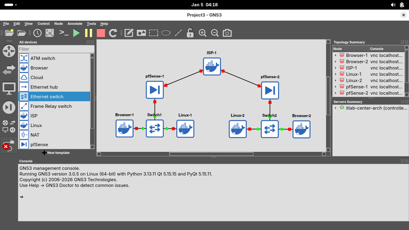
Now that our topology is physically created we must configure it before making our Virtual Private Network
Right click on the ISP node and click Start, you should see its connections turn green to show that its on:
We will assume the role of the ISP provisioning public IP Addresses to our customers in the next few steps
Right click on the ISP Router node and select Console, this will pull up the nodes command line interface:
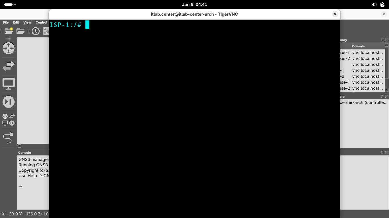
Run the following commands from the ISP Routers VNC Terminal to set each of the networks Public IP Address:
ISP-1:/# vtysh
ISP-1# conf t
ISP-1(config)# interface eth0
ISP-1(config-if)# ip address 198.51.100.1/24
ISP-1(config-if)# exit
ISP-1(config)# interface eth1
ISP-1(config-if)# ip address 203.0.113.1/24
ISP-1(config-if)# end
ISP-1# exit
We have set the network IP Addresses, our final provisioning step as the ISP is to assign them with DHCP
We want a configuration that will automatically assign these IP addresses to any device on the other end
This is what happens in your home when you connect the COAX cable, known as the Provider Edge (PE) Handoff
Run the following commands from the ISP Routers VNC Terminal to configure the Provider Edge (PE) Handoff:
ISP-1:/# cat <<EOF > /etc/dnsmasq.conf
> interface=eth0
> dhcp-range=interface:eth0,198.51.100.3,198.51.100.3,255.255.255.0,1h
> dhcp-option=eth0,3,198.51.100.1
> interface=eth1
> dhcp-range=interface:eth1,203.0.113.5,203.0.113.5,255.255.255.0,1h
> dhcp-option=eth1,3,203.0.113.1
> EOF
ISP-1:/# pkill dnsmasq
ISP-1:/# dnsmasq --conf-file=/etc/dnsmasq.conf
We have completed our duties as the Internet Service Provider and provisioned public IPs for our customers
Now let's assume the role of the network administrators and provision each local network private IP address
Right click on each of the pfSense appliances and click start, then right-click pfSense-1 and hit Console:
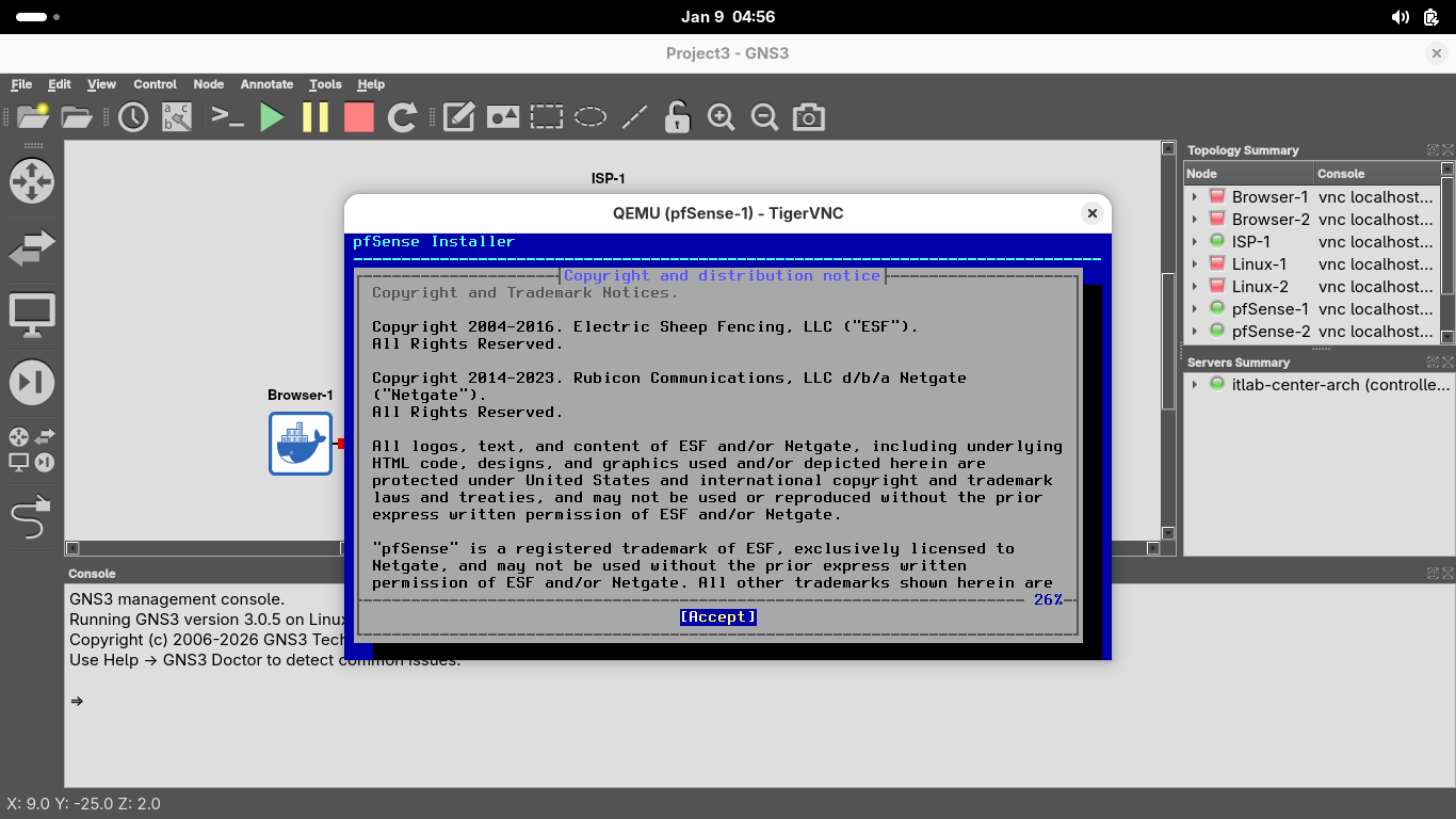
Press Enter a few times until you are prompted to select the disk, press space to select the disk below:
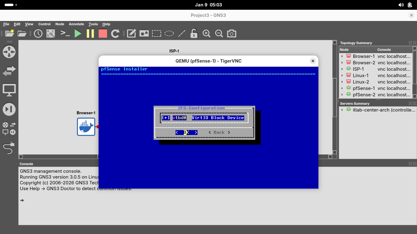
Now press enter to proceed, when prompted if we want to destroy disk contents, press tab to select yes:
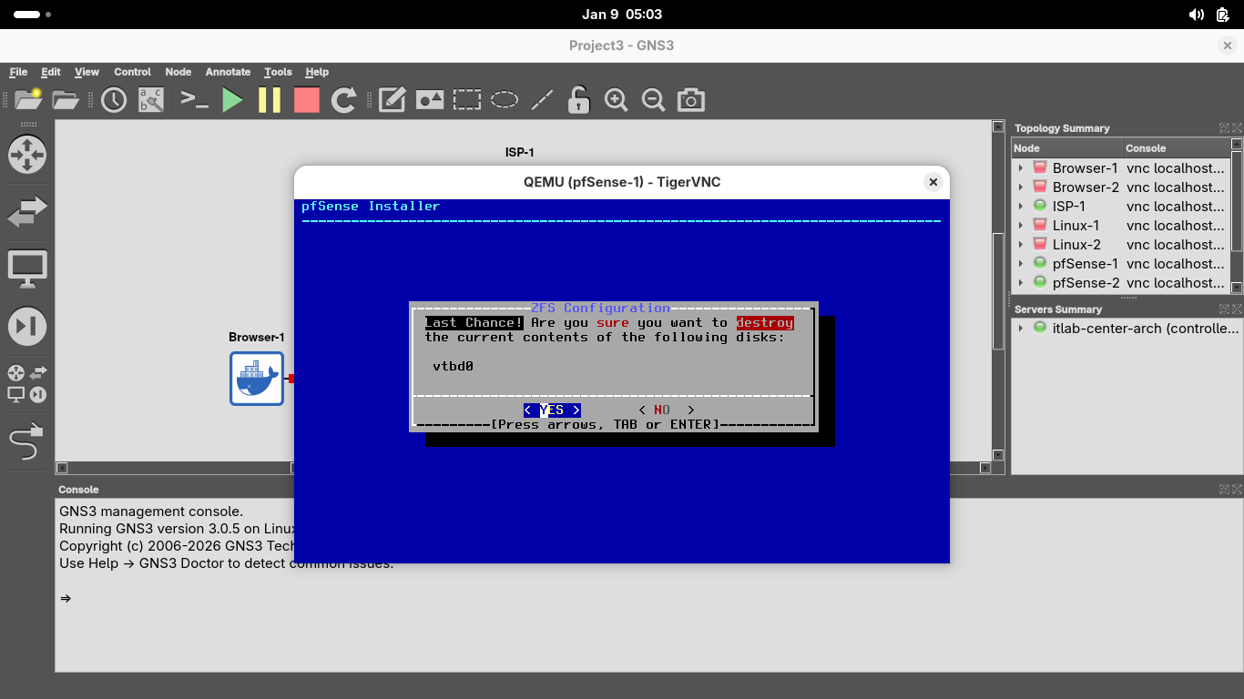
This may take some time, but once the installation is complete you will be prompted to reboot, hit enter:

We can see that both interfaces have assigned IP addresses, now let's close the pfSense-1 nodes terminal
The pfSense appliance automatically chooses 192.168.1.1/24 for the LAN, let's keep that for our first LAN
Right click on the pfSense-2 node and select Console, install the pfSense appliance just as done previous:
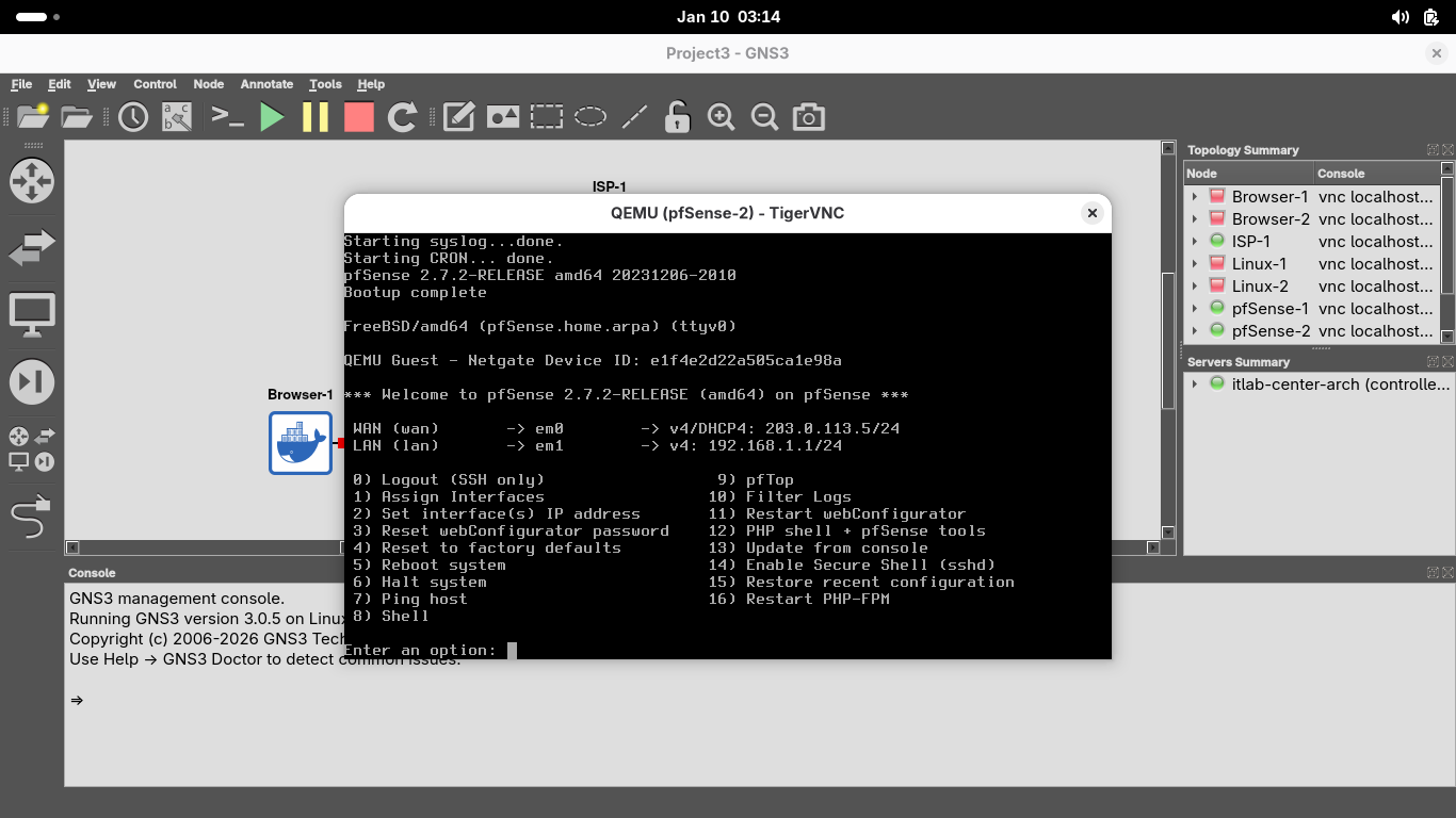
Now let's go ahead and type 2 and hit enter twice, type n and hit enter, then type 10.10.10.1/24 + Enter
When prompted press enter to select no gateway and type n and press enter twice to skip IPv6 configuration
When prompted to enable the DHCP server on LAN, type y and hit enter, then type 10.10.10.2 and hit enter
To set the end of the address range type 10.10.10.255 and hit enter, then type y and hit enter to finish:

Now that the local IP is set, close out of the pfSense-2 nodes terminal. We are ready to begin the lesson
7. Validate Connectivity
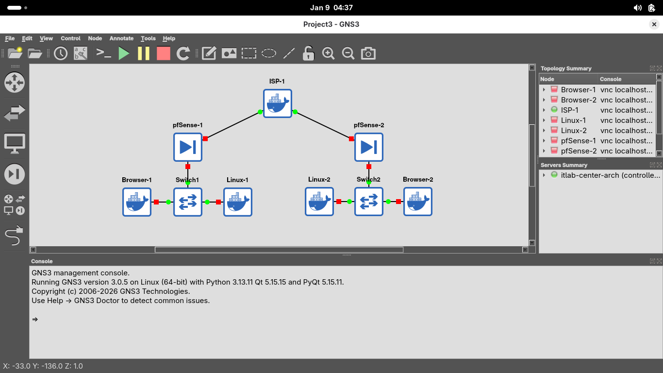
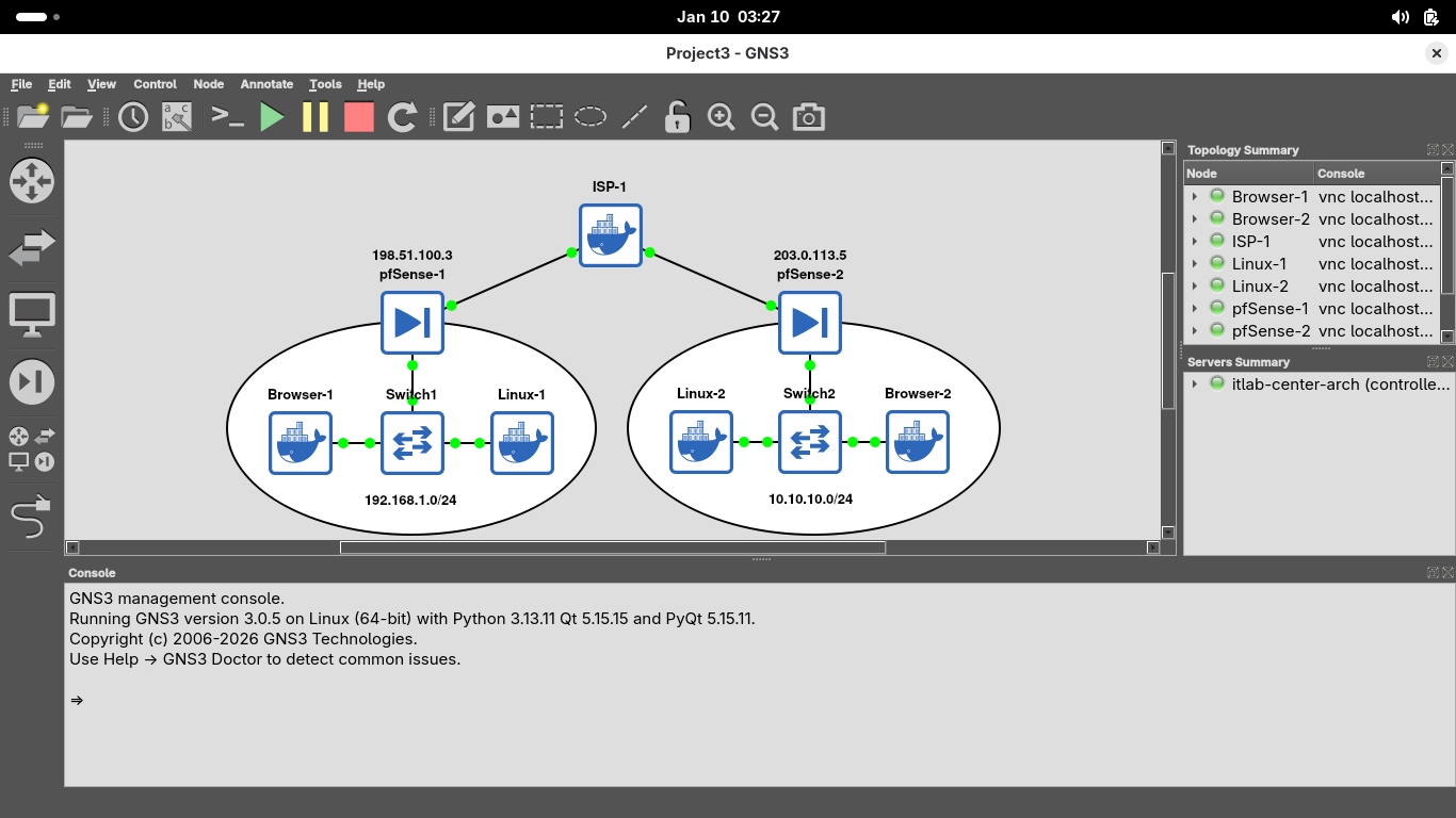
On the GNS3 control bar, click the Start button to power on all the devices and watch the links turn green
This topology shows two networks (192.168.1.0/24 and 10.10.10.0/24) behind firewalls connected to an ISP
This lab will guide you through setup of a site-to-site VPN tunnel on the firewalls so networks can talk
Before we configure our VPN, we will access the pfSense-1 Firewall and validate it can talk to pfSense-2
In the topology windows, right-click the Browser-1 hosts and select Console to open the Firefox Browser:
In the web browser, type 192.168.1.1 in the Address bar and click Advanced > Accept the Risk and Continue:
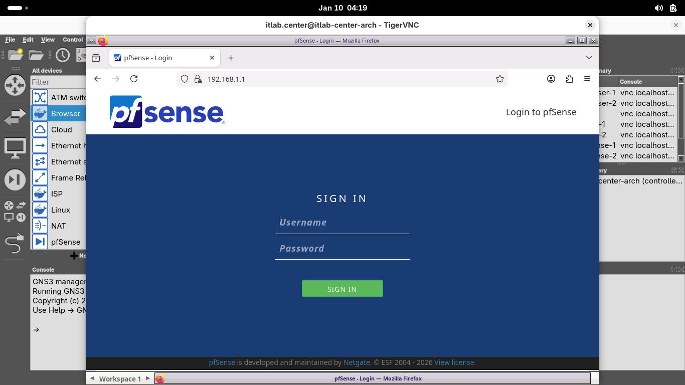
Login with the default credentials admin and pfsense, the system prompts you to complete the initial setup:
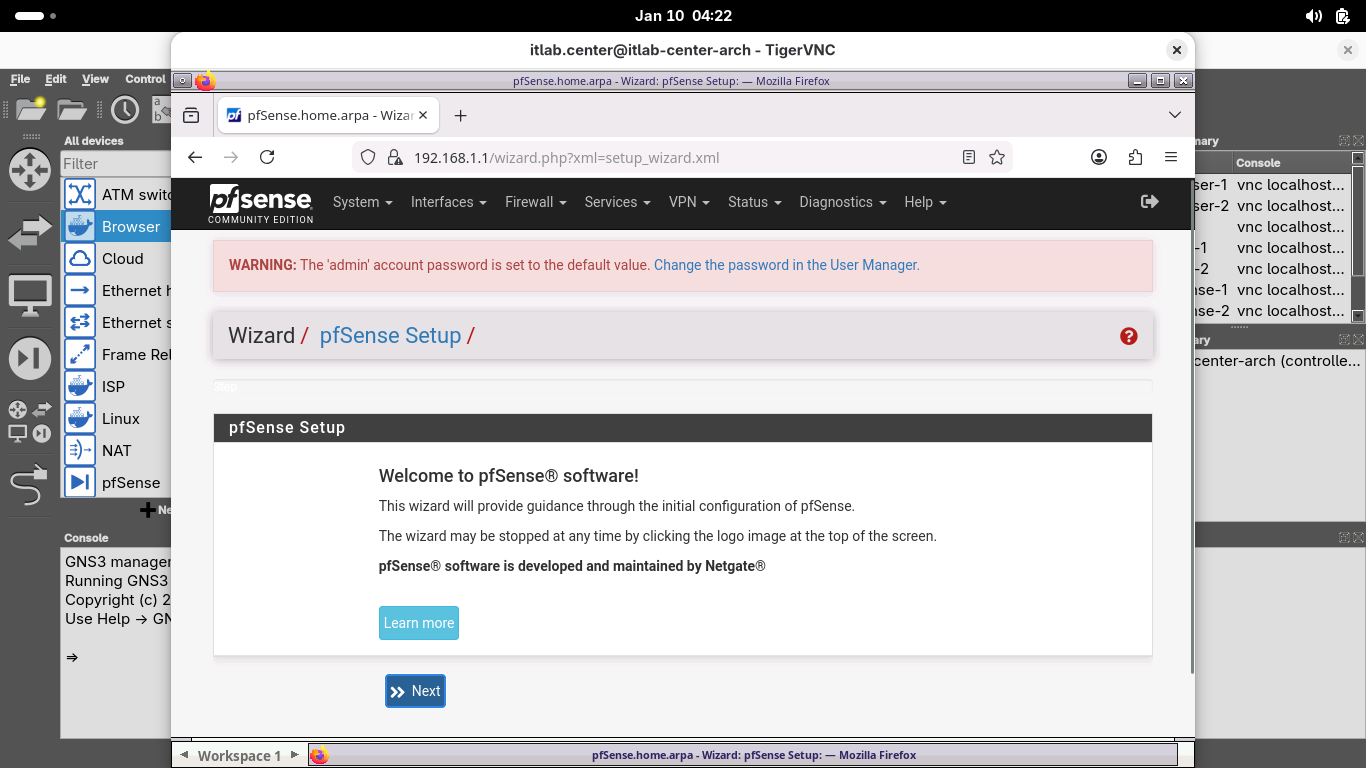
Scroll down to select next and complete the web GUI first time setup with the following network options:
• Hostname: pfSense-1
• Domain: home.arpa
• Primary DNS Server: 1.1.1.1
• Secondary DNS Server: 8.8.8.8
• Override DNS: Keep Checked
All other configuration settings can remain unchanged, the system will also make you create a password
It will also prompt you to perform a reload for the changes to take affect, click finish once complete:
Now head to the console on browser-2 and head to 10.10.10.1 to configure that pfSense with these options:
• Hostname: pfSense-2
• Domain: home.arpa
• Primary DNS Server: 1.1.1.1
• Secondary DNS Server: 8.8.8.8
• Override DNS: Keep Checked
All other configuration settings can remain unchanged, the system will also make you create a password
It will also prompt you to perform a reload for the changes to take affect, click finish once complete:

Remaining in our browser-2, from the menu at the top head to Firewall > Rules to view all the WAN rules:
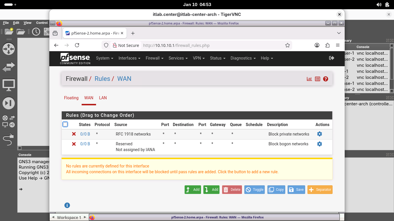
We want to test connectivity between the two firewalls, so we must add a rule for ICMP traffic to the WAN
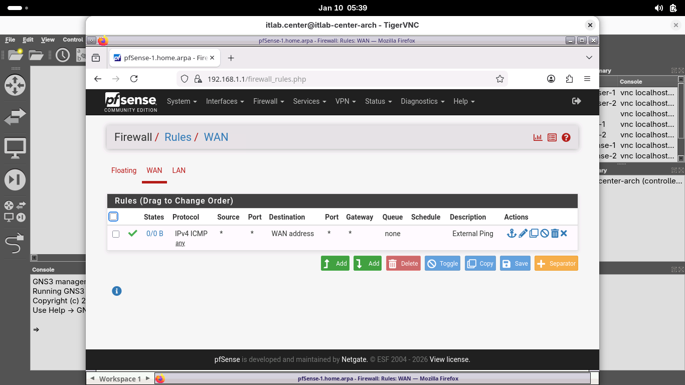
Click the Add button, then add a new rule with the following Attributes to allow for external IP pings:
• Action: Pass
• Disabled: Leave Unchecked
• Interface: WAN
• Address Family: IPv4
• Protocol: ICMP
• ICMP Subtypes: Any
• Source: Any
• Destination: WAN Address
• Log: Leave Unchecked
• Description: External Ping
Click save, then click apply changes to apply the new rule, now head to Interfaces > WAN to view the WAN
Scroll to the bottom and uncheck Block private networks and loopback addresses and Block Bogon Networks
Click save and then click apply, browser-2 is ping ready, now back to browser-1 and create the same rule:
This rule is not required for a VPN to work, but it is helpful in ensuring that a remote site is reachable
From the pfSense menu bar, click Diagnostics and select Ping to open the web browsers Ping diagnostics tool
On the Diagnostics /Ping page, type 203.0.113.5 in the hostname field, then click ping to test connection:
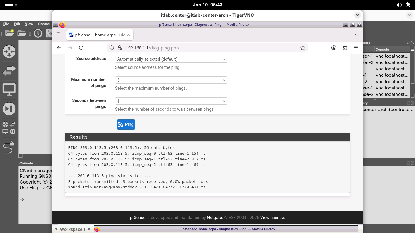
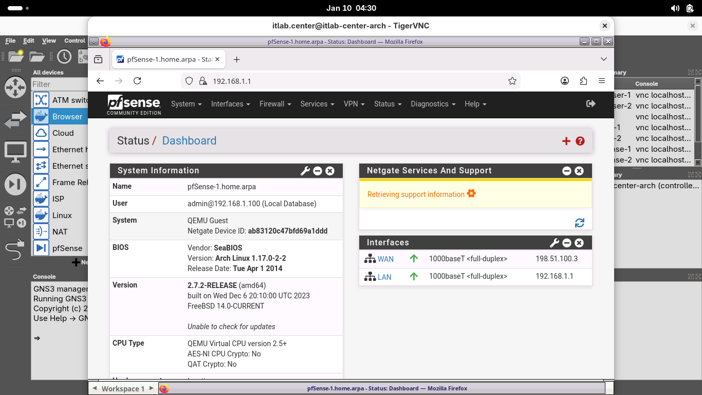
Our firewall appliances are each online and can communicate with each other over the internet via public IP
8. Configure the pfSense-1 VPN
Now that we know that pfSense-2 is reachable, let's configure the pfSense-1 side of the site-to-site VPN
For our setup, pfSense-1 will create the connection, known as the initiator, and pfSense-2 is the receiver
Once we have both sides of the VPN configured, we will manually start the VPN tunnel on the pfSense-1 node
From the pfSense menu bar on pfSense-1, click VPN and select IPsec to open the VPN / IPsec / Tunnels page:
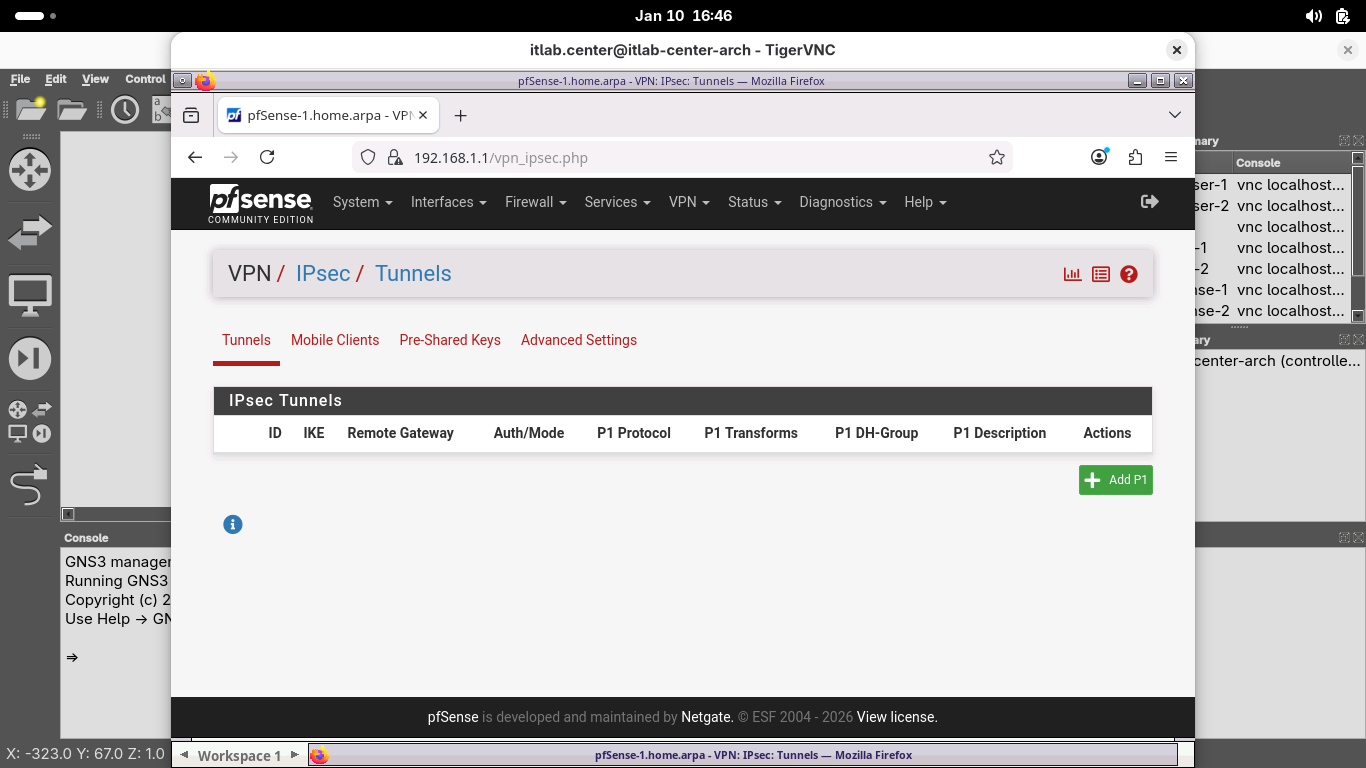
As we learned in the Overview, IPsec creates two tunnels: one for Authentication and one for Encryption
IKE Phase 1 and IKE Phase 2 respectively, on the pfSense firewall these are referred to as P1 and as P2
From the VPN / IPsec / Tunnels page, click Add P1 to create a new IKE Phase 1 Security Association (SA):
From the VPN / IPsec / Tunnels / Edit Phase 1 page, enter the following details, then click save below:
• Description: Connection to pfSense-2
• Remote Gateway: 203.0.113.5
• Pre-Shared Key: itlabdotcenter
• Encryption Algorithm: Set the Key Length to 256 Bits
• Child SA Close Action: Restart/Reconnect
For the purposes of this lab, we are using pre-shared keys since they are easier than using certificates
However, a short key would be insecure, in a production system you should always use longer key lengths
On the VPN / IPsec / Tunnels page, click Apply Changes and wait for the new Phase 1 SA to be activated:
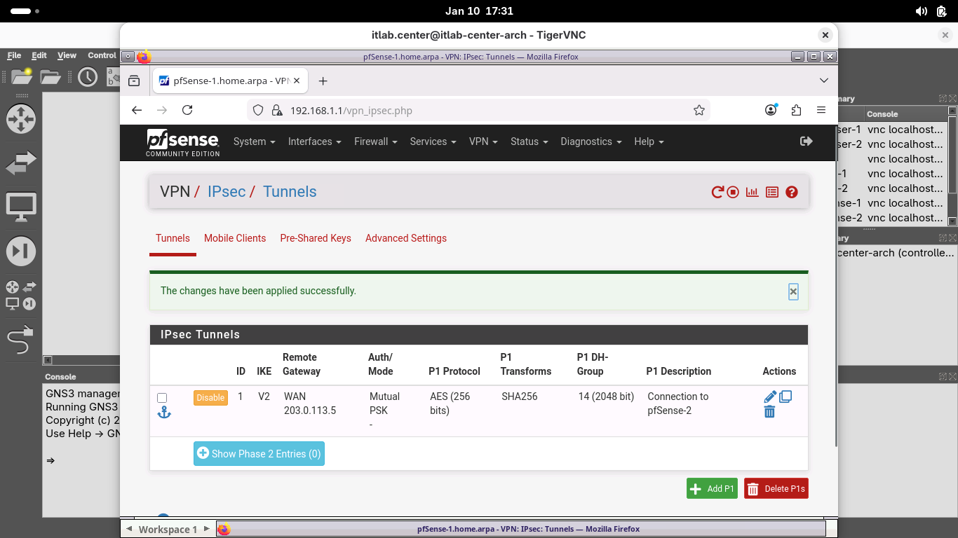
From the VPN / IPsec / Tunnels page, under the new configured Phase 1 SA, click Show Phase 2 Entries (0)
Click Add P2 and enter the following details to create a new IKE Phase 2 Security Association, then save:
• Description: pfSense-2
• Remote Network: Network 10.10.10.0 / 24
• Encryption Algorithms: AES192-GCM / Auto Only
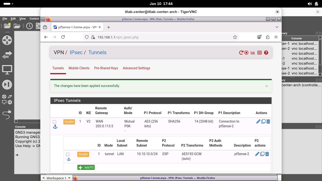
On the VPN / IPsec / Tunnels page, click Apply Changes and wait for the new Phase 2 SA to be activated
From the VPN / IPsec / Tunnels page, under the Phase 1 SA, click Show Phase 2 Entries (1) to view the SA:
From the menu bar at the top, click Firewall and select Rules, then select the IPsec table to open IPsec:
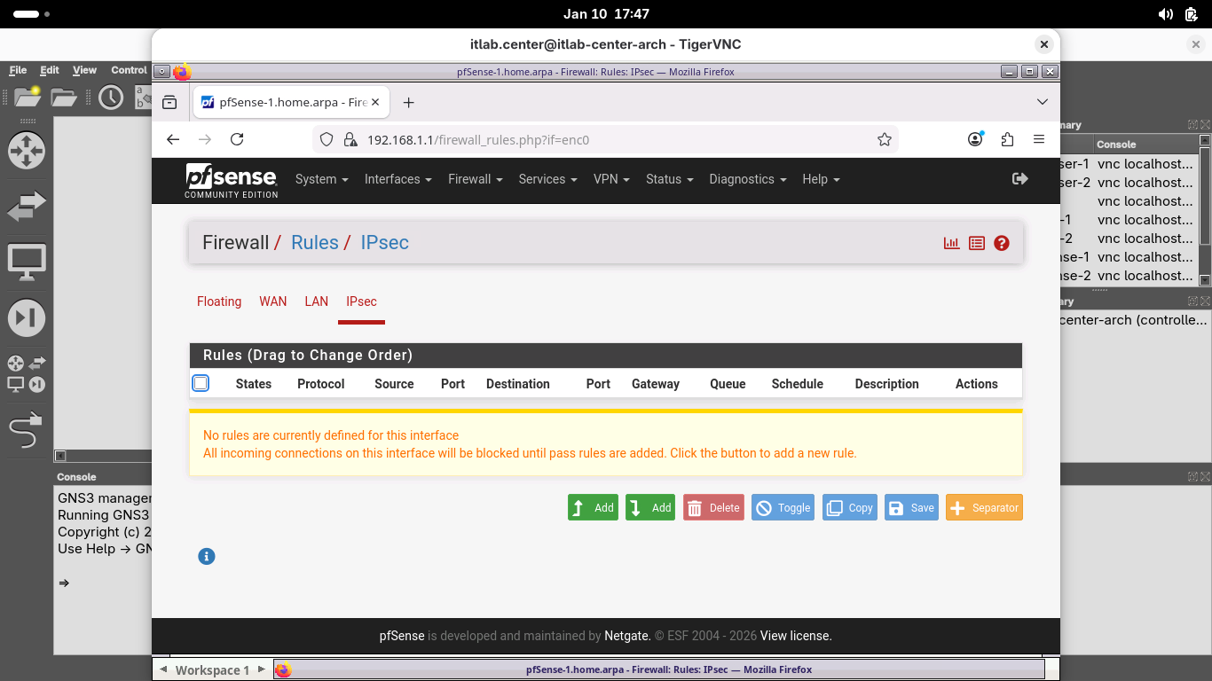
Click the Add button, then add a new rule with the following Attributes to allow for IPsec tunnel traffic:
• Protocol: Any
• Source: Network 10.10.10.0 / 24
• Destination: LAN Subnets
Click save, then click apply changes to apply the new rule, when completed your rule should match below:
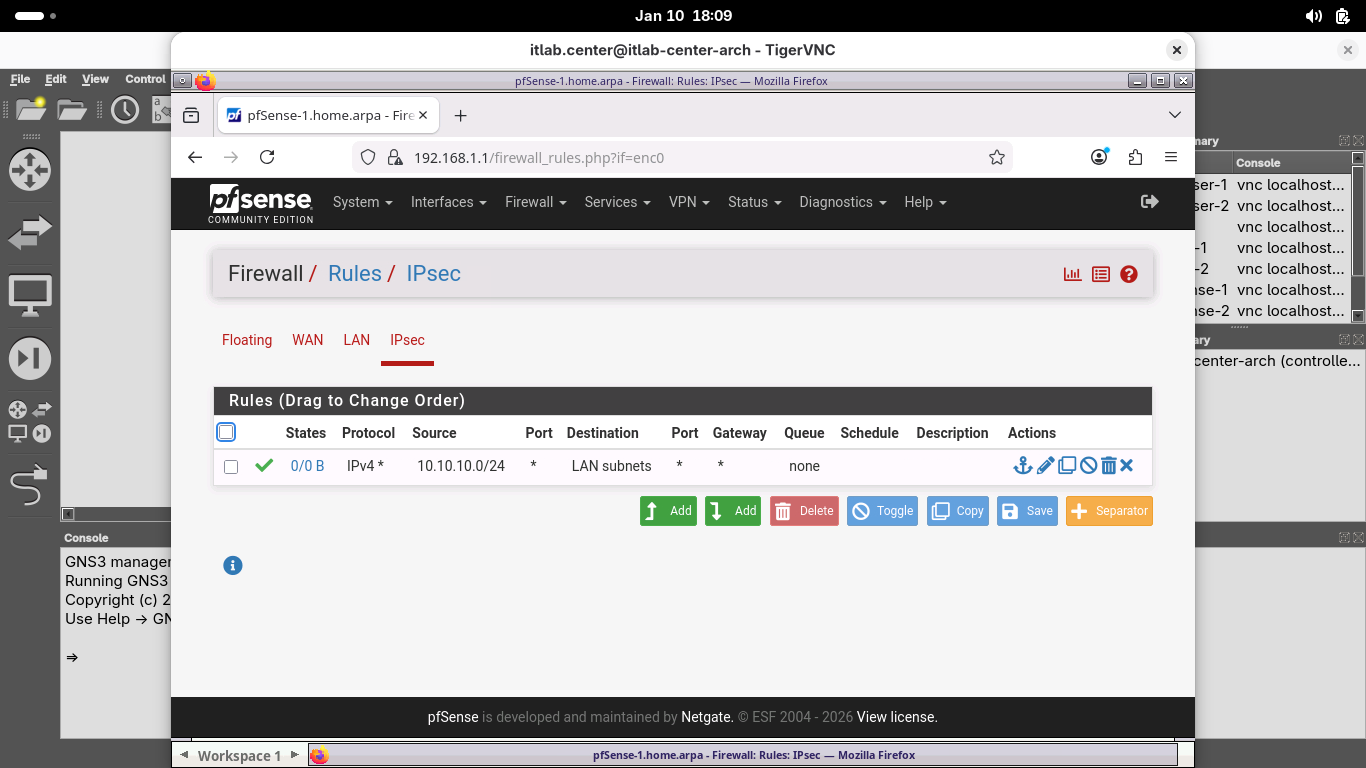
While this rule would be overly permissive for a production environment, it is a good rule for testing
9. Configure the pfSense-2 VPN
Now, let's configure the other side of the site-to-site VPN, head back to the web browser on browser-2
From the pfSense menu bar on pfSense-2, click VPN and select IPsec to open the VPN / IPsec / Tunnels page:

From the VPN / IPsec / Tunnels page, click Add P1 to create a new IKE Phase 1 Security Association (SA):
From the VPN / IPsec / Tunnels / Edit Phase 1 page, enter the following details, then click save below:
• Description: Connection to pfSense-1
• Remote Gateway: 198.51.100.3
• Pre-Shared Key: itlabdotcenter
• Encryption Algorithm: Set the Key Length to 256 Bits
• Life Time: 31680
• Child SA Start Action: None (Responder Only)
• Child SA Close Action: Close Connection and Clear SA
On the VPN / IPsec / Tunnels page, click Apply Changes and wait for the new Phase 1 SA to be activated:

From the VPN / IPsec / Tunnels page, under the new configured Phase 1 SA, click Show Phase 2 Entries (0)
Click Add P2 and enter the following details to create a new IKE Phase 2 Security Association, then save:
• Description: pfSense-1
• Remote Network: Network 192.168.1.0 / 24
• Encryption Algorithms: AES192-GCM / Auto Only
• Life Time: 5400
On the VPN / IPsec / Tunnels page, click Apply Changes and wait for the new Phase 2 SA to be activated
From the VPN / IPsec / Tunnels page, under the Phase 1 SA, click Show Phase 2 Entries (1) to view the SA:
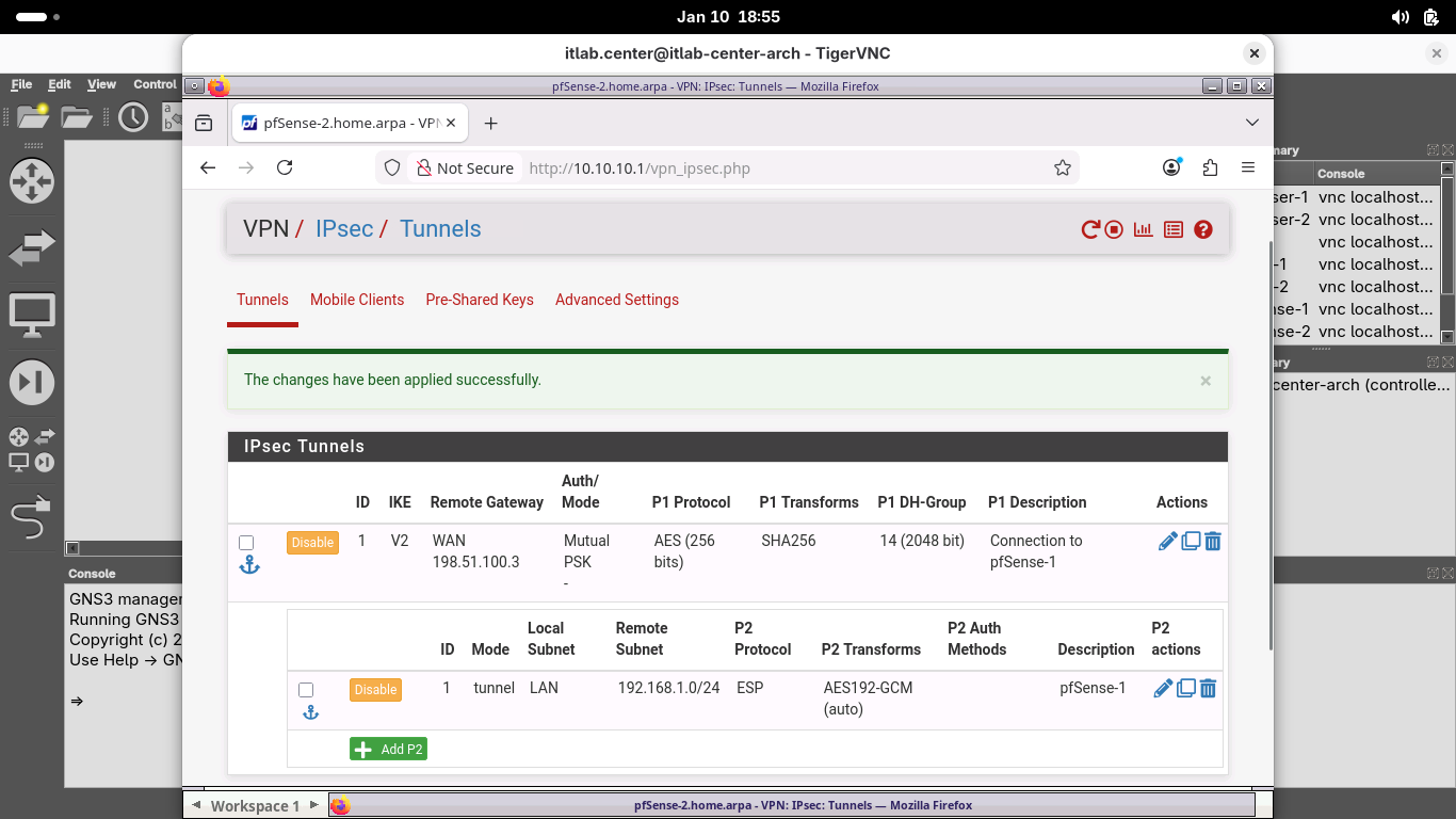
From the menu bar at the top, click Firewall and select Rules, then select the IPsec table to open IPsec:
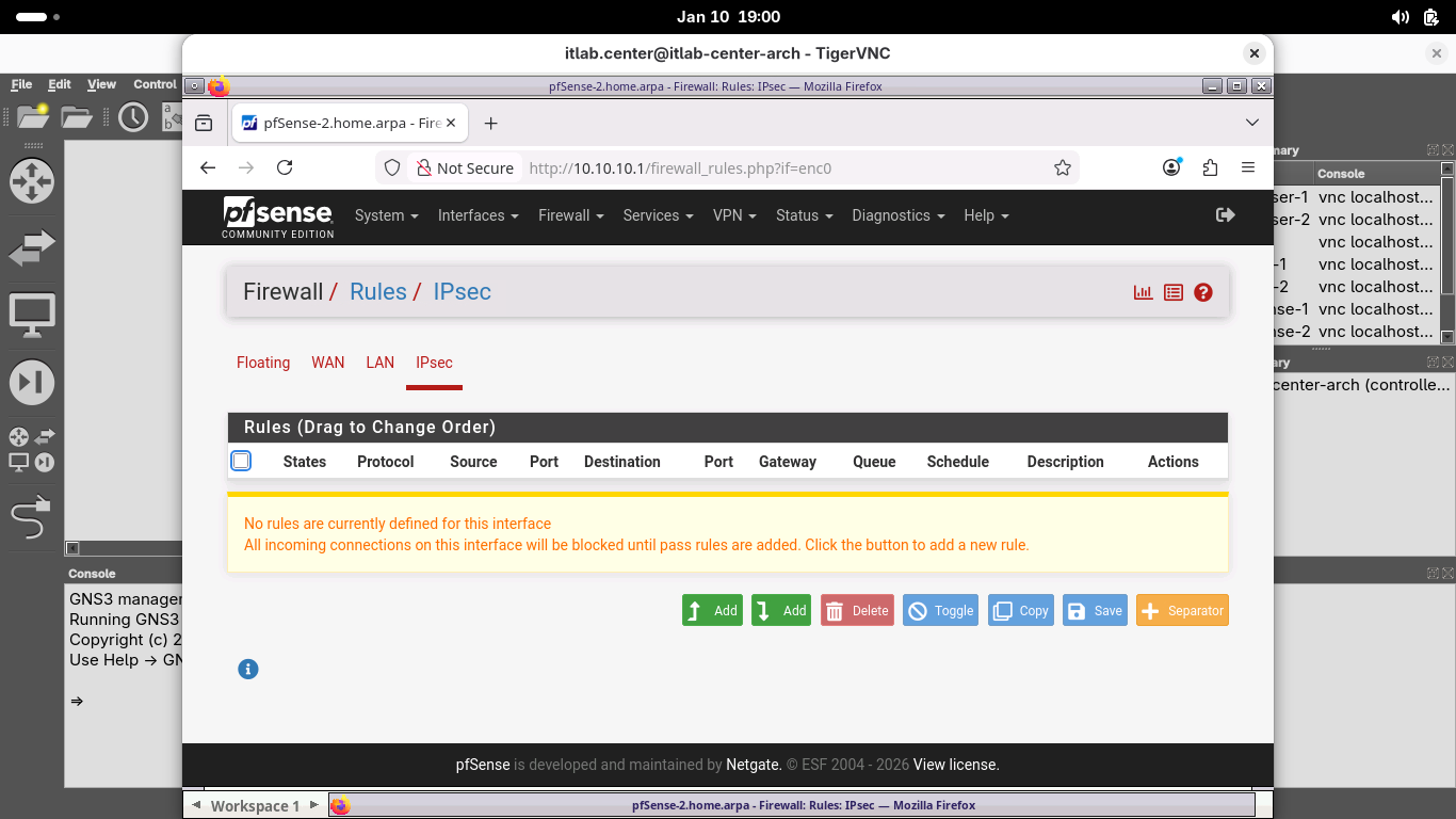
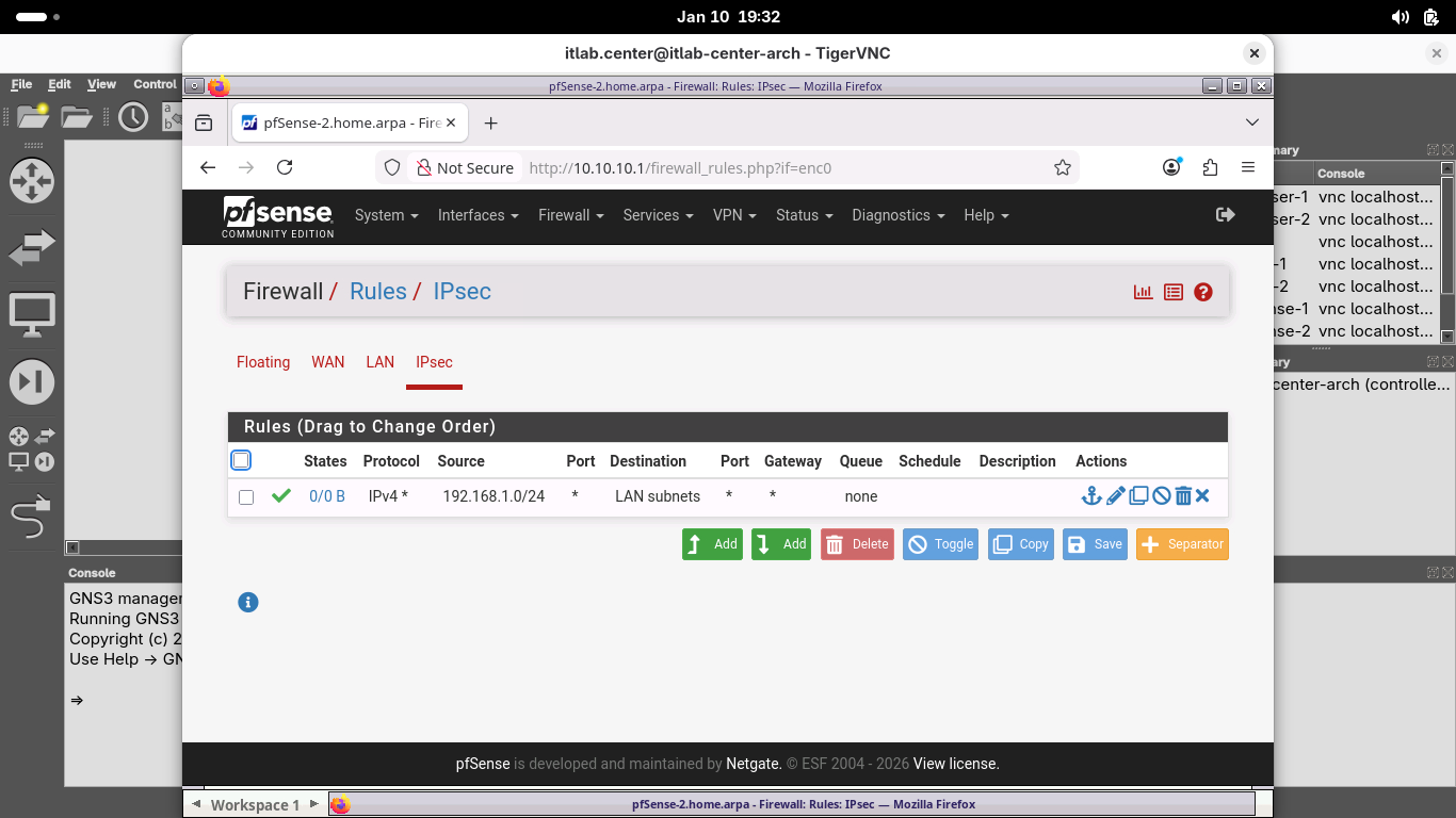
Click the Add button, then add a new rule with the following Attributes to allow for IPsec tunnel traffic:
• Protocol: Any
• Source: Network 192.168.1.0 / 24
• Destination: LAN Subnets
Click save, then click apply changes to apply the new rule, when completed your rule should match below:
Now that our Network Edges are configured to create the tunnel and allow the traffic, let's hit the switch
10. Activate the Site-to-Site VPN
Now that we've configured both sides of our site-to-site VPN, we will activate it and verify connectivity
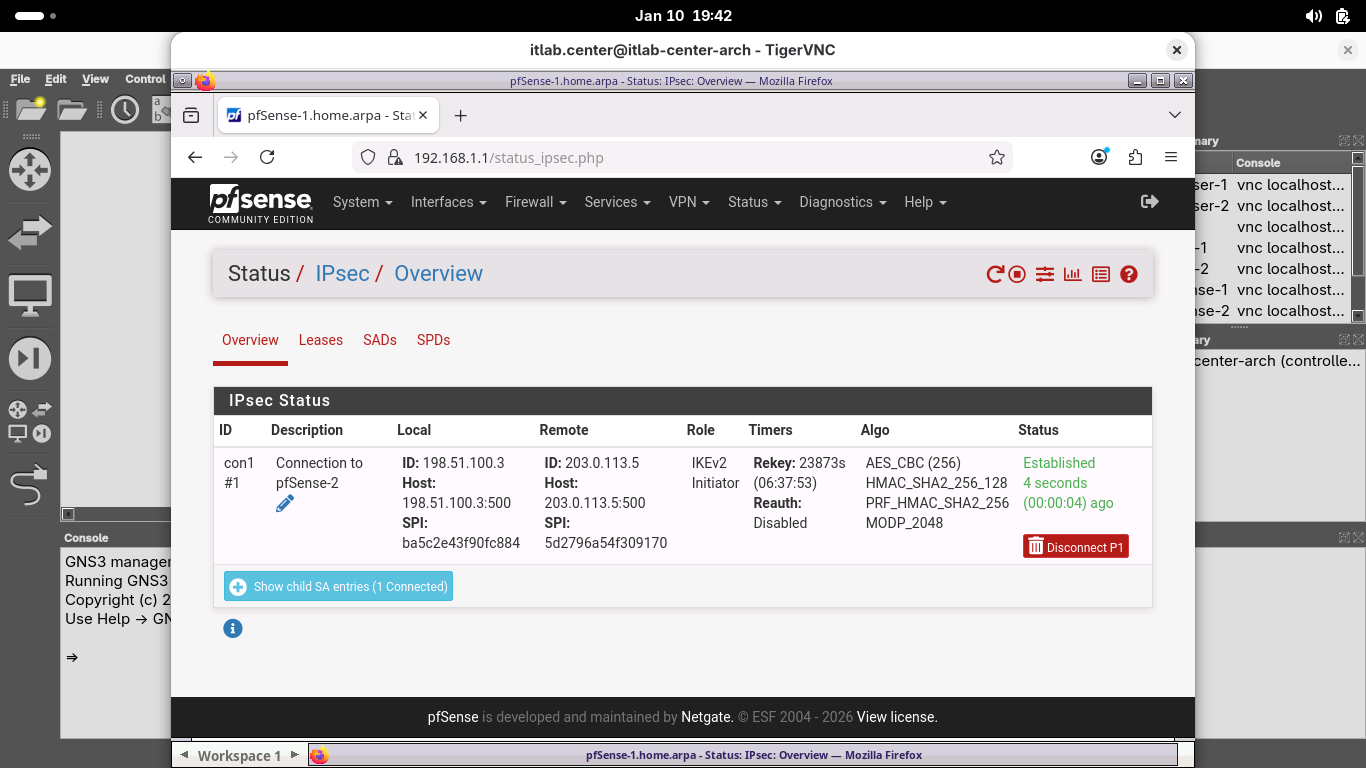
Head back to the Browser-1 window. From the pfSense menu bar click Status and then select the IPsec option:
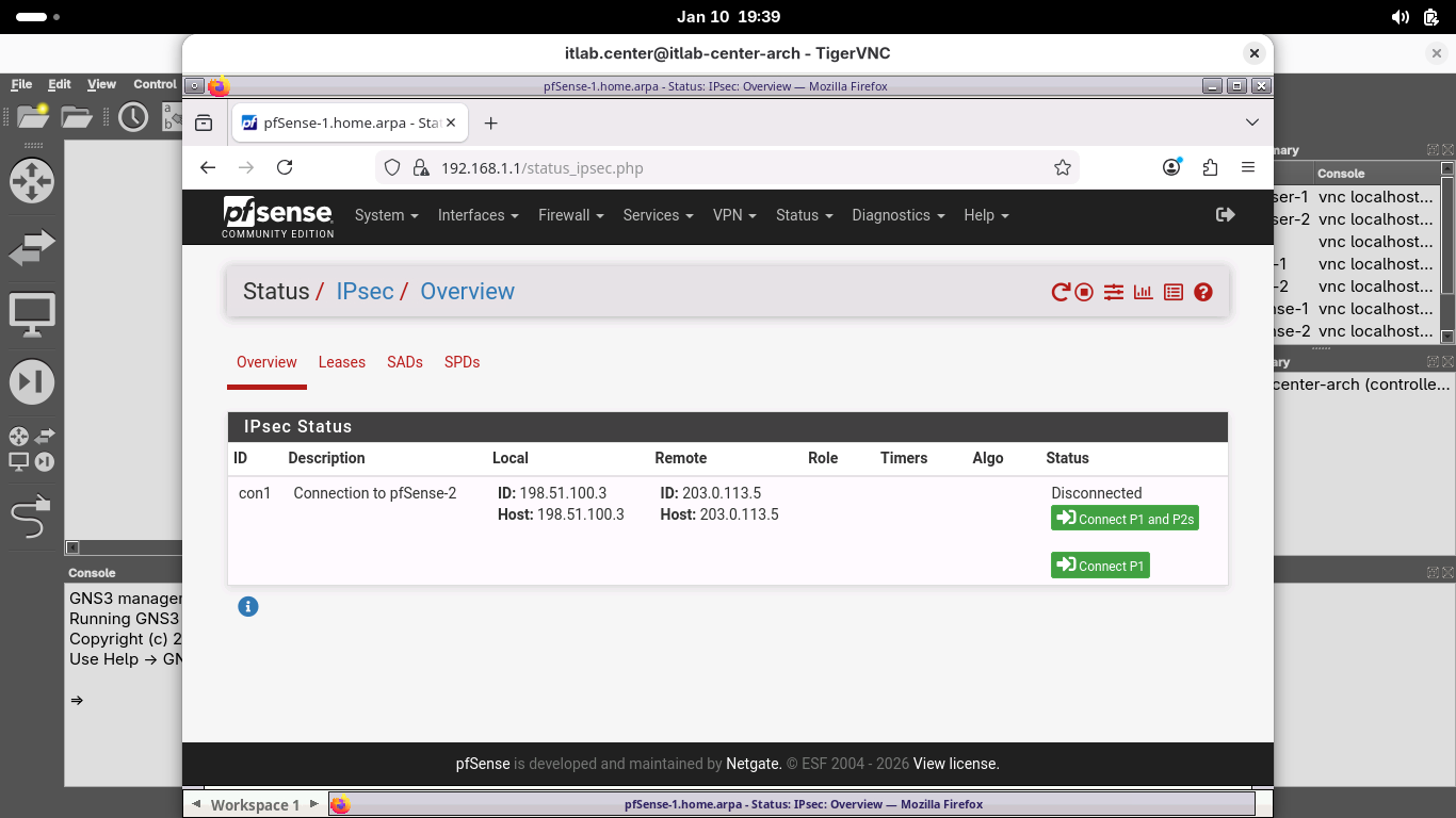
From the Status / IPsec / Overview page, click Connect P1 and P2s to activate the site-to-site VPN tunnel:
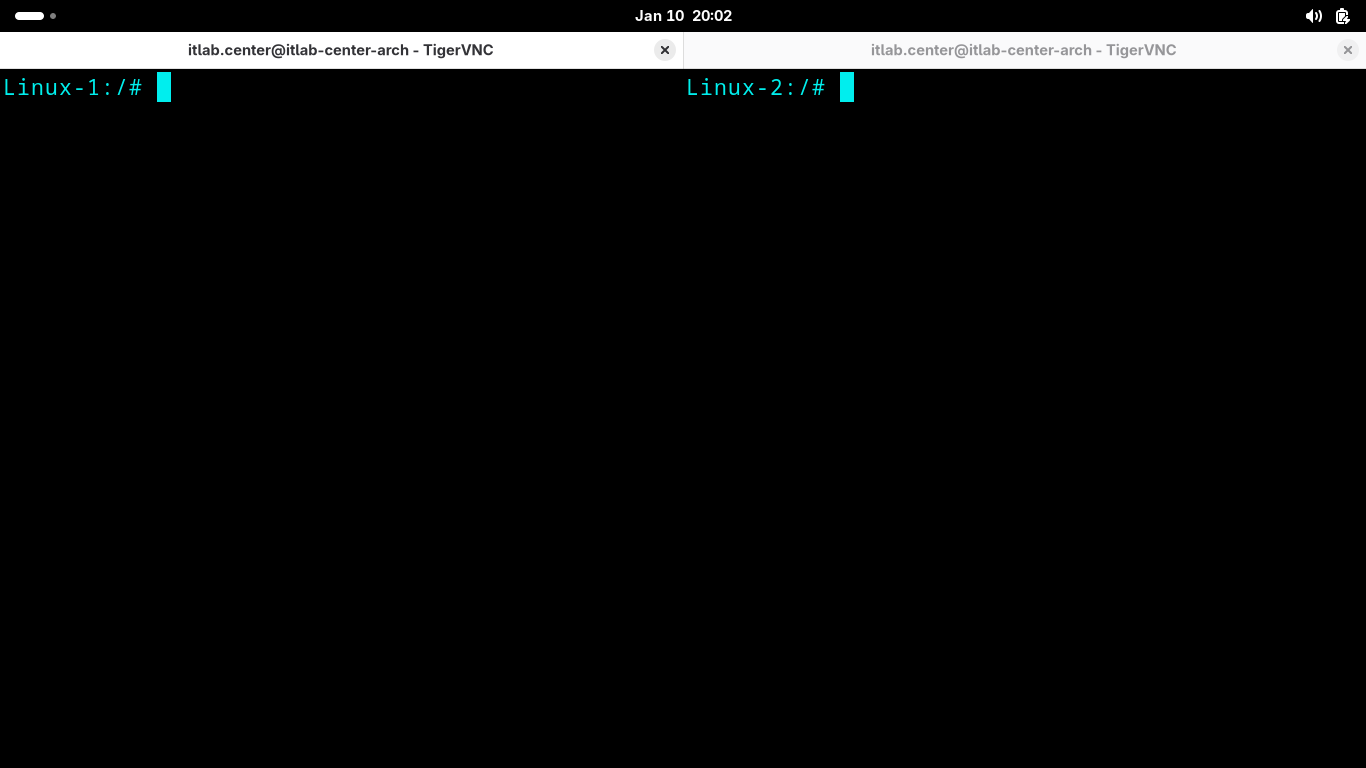
From the GNS3 topology window, right click Linux-1 and select Console. Do the same with the Linux-2 node:
Run the following command from both Linux-1 and Linux-2 Alpine Terminal to discover the hosts IP Addresses:
Linux-1:/# ip addr show
Linux-2:/# ip addr show
Resulting Output:
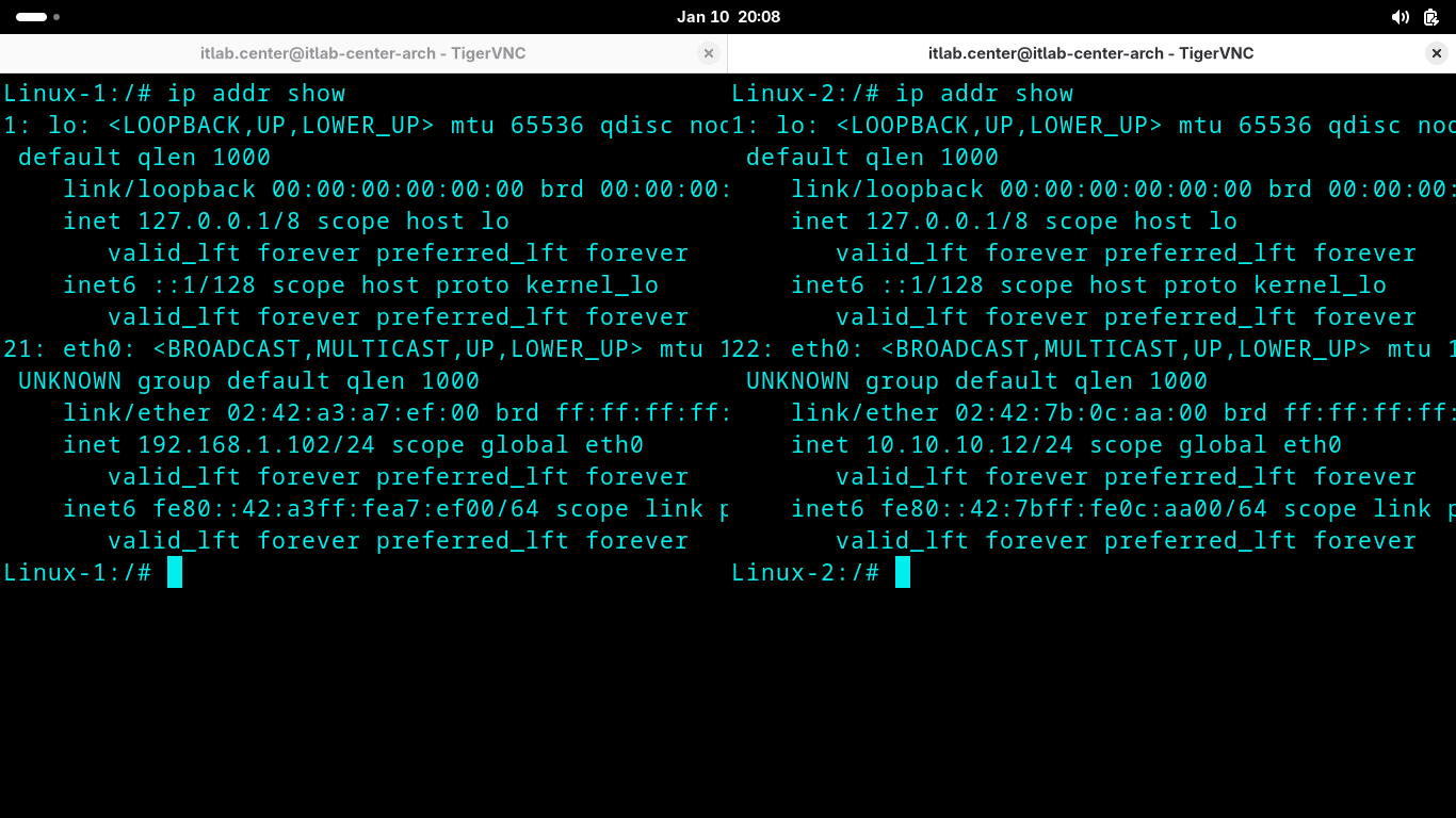
We can see that in the example Linux-1 has 192.168.1.102 and Linux-2 has 10.10.10.12, but yours may differ
For these next few commands, adjust the IP addresses for each host to properly match your lab environment
Run the following commands from both Linux-1 and Linux-2 Alpine Terminal to test the VPN with a local ping:
Linux-1:/# ping -c 8 10.10.10.12
Linux-2:/# ping -c 8 192.168.1.102
Resulting Output:
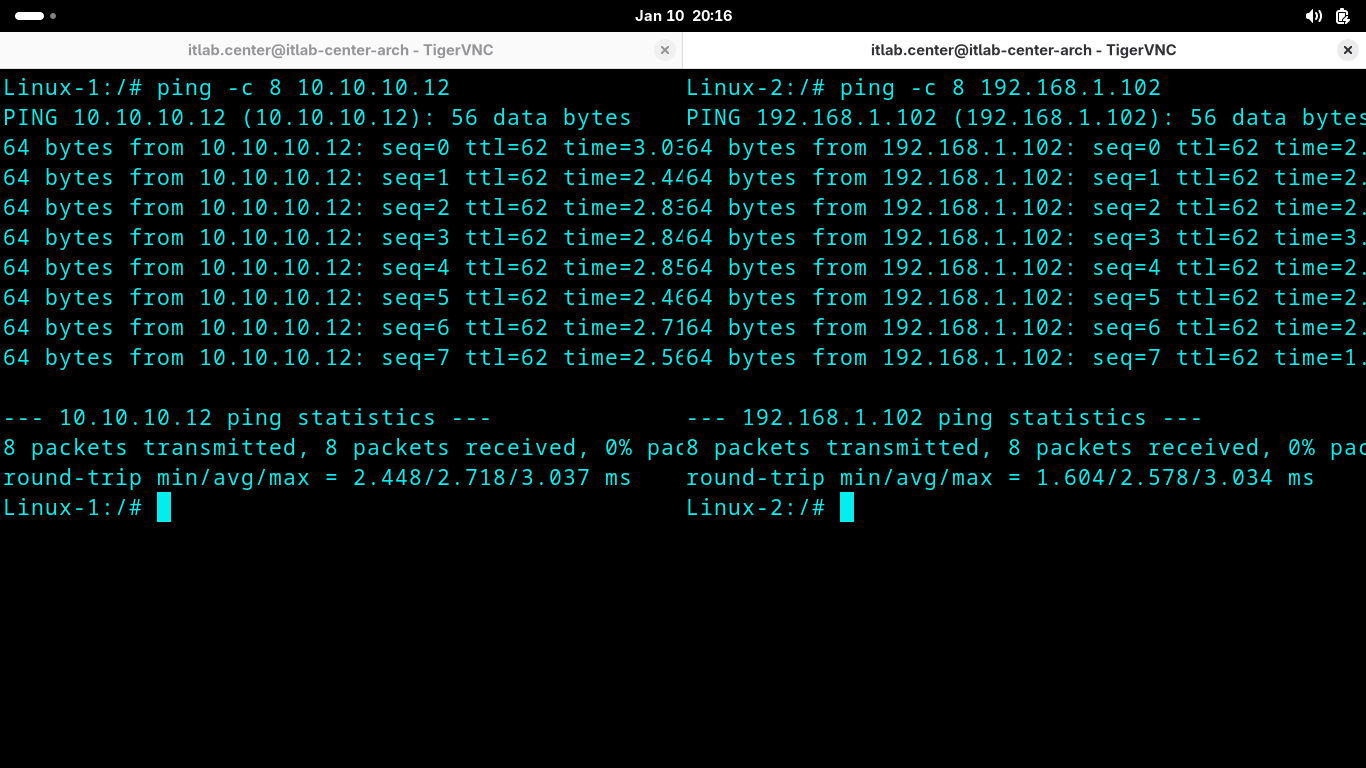
Notice that each host can ping the other as if it were a local resource physically connected to each other
The VPN tunnel and the firewall rules have connected the two remote networks into a logical virtual LAN
Run the following commands from both Linux-1 and Linux-2 Alpine Terminal to see how the packets travel:
Linux-1:/# traceroute 10.10.10.12
Linux-2:/# traceroute 192.168.1.102
Resulting Output:
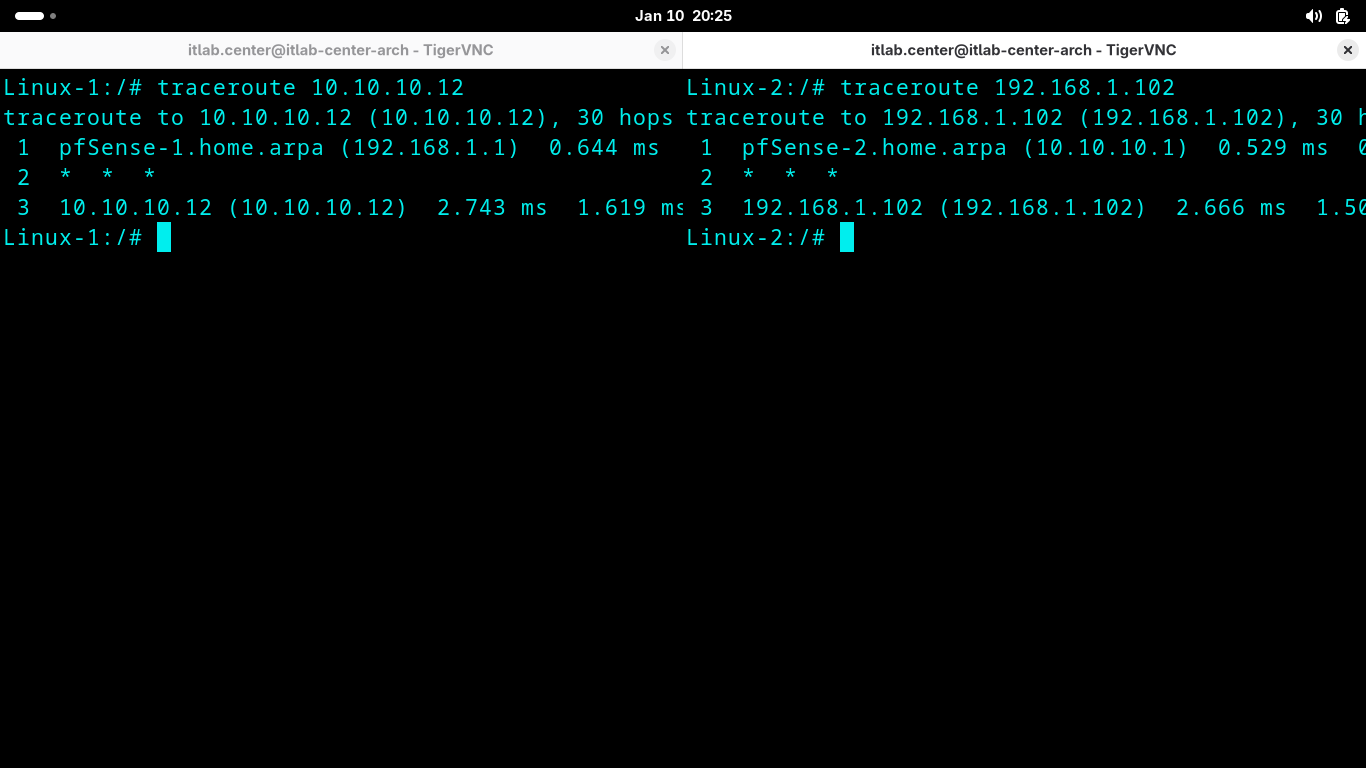
Interesting, you may expect to see each pfSense node along with the ISP Router along this packets journey
But instead we can only see LAN to LAN. This is because the VPN creates an encrypted tunnel for the packet
Congratulations! In this lesson, you created and tested a site-to-site tunnel using IPsec in tunnel mode